Impact Factor
- Issue 14; 2026
- Issue 13; 2026
- Issue 12; 2026
- Issue 11; 2026
- Issue 10; 2026
- Volume 16; 2026
- Advance Articles
- Past Issues
- Cover Images
- Cover Suggestion
- Index & Coverage
- Special Issues
1. Introduction
2. Oocyte micromanipulation
3. Oocyte electrical...
4. Early embryo in vitro culture
5. Conclusion and prospect
Acknowledgements
Supplementary Material
References
International Journal of Biological Sciences
International Journal of Medical Sciences
 Global reach, higher impact

Theranostics 2021; 11(15):7391-7424. doi:10.7150/thno.58799 This issue Cite
Review
Recent advances in critical nodes of embryo engineering technology
Youwen Ma1#, Mingwei Gu1#, Liguo Chen1, Hao Shen1, Yifan Pan1, Yan Pang1, Sheng Miao1, Ruiqing Tong2, Haibo Huang1 ![]() , Yichen Zhu3
, Yichen Zhu3 ![]() , Lining Sun1,4
, Lining Sun1,4
1. School of Mechanical and Electric Engineering, Jiangsu Provincial Key Laboratory of Advanced Robotics, Soochow University, Suzhou 215123, China.
2. Cardiology, Dushuhu Public Hospital Affiliated to Soochow University, Suzhou 215000, China.
3. Jiangsu Key Laboratory of Neuropsychiatric Diseases and Cambridge-Suda Genomic Resource Center, Soochow University, Suzhou 215123, China.
4. State Key Laboratory of Robotics & Systems, Harbin Institute of Technology, Harbin, China.
#These authors contributed equally to this work.
Received 2021-1-29; Accepted 2021-5-13; Published 2021-5-25
Abstract

The normal development and maturation of oocytes and sperm, the formation of fertilized ova, the implantation of early embryos, and the growth and development of foetuses are the biological basis of mammalian reproduction. Therefore, research on oocytes has always occupied a very important position in the life sciences and reproductive medicine fields. Various embryo engineering technologies for oocytes, early embryo formation and subsequent developmental stages and different target sites, such as gene editing, intracytoplasmic sperm injection (ICSI), preimplantation genetic diagnosis (PGD), and somatic cell nuclear transfer (SCNT) technologies, have all been established and widely used in industrialization. However, as research continues to deepen and target species become more advanced, embryo engineering technology has also been developing in a more complex and sophisticated direction. At the same time, the success rate also shows a declining trend, resulting in an extension of the research and development cycle and rising costs. By studying the existing embryo engineering technology process, we discovered three critical nodes that have the greatest impact on the development of oocytes and early embryos, namely, oocyte micromanipulation, oocyte electrical activation/reconstructed embryo electrofusion, and the in vitro culture of early embryos. This article mainly demonstrates the efforts made by researchers in the relevant technologies of these three critical nodes from an engineering perspective, analyses the shortcomings of the current technology, and proposes a plan and prospects for the development of embryo engineering technology in the future.
Keywords: oocytes, embryo engineering technology, micromanipulation, electrical activation, electrofusion, in vitro culture
1. Introduction
Oocytes are formed by two meiotic divisions of oogonia. In the natural fertilization state, when the sperm passes through the uterus and fallopian tubes, the layer of disabling factor on the surface of the sperm secreted from the epididymis is removed; thus, the sperm has the capacity to fertilize an ovum. The sperm contacts the zona pellucida and binds to the sperm receptor (ZP3). Under the action of acrolein and N-amidase, the sperm nucleus and cytoplasm enter the cytoplasm of the oocyte through the zona pellucida. At this time, a large number of cortical granules in the outer cytoplasm below the oocyte membrane release their content into the perivitelline space, causing changes in the ZP3 glycoprotein molecules in the zona pellucida and causing the zona pellucida to lose its function of accepting sperm penetration. The reaction prevents the occurrence of multiple inseminations and polyspermy and ensures the biological characteristics of human monospermy. Under the stimulation of sperm penetration, the oocyte recovers and quickly completes the second meiosis II, forming a mature oocyte, and the second polar body is discharged into the perivitelline space. Since then, the male and female pronuclei are formed separately, and chromosomes are replicated at the same time. The double pronuclei move closer to the middle and merge to form a diploid zygote, and the fertilization process ends. Therefore, the number, morphology and mobility of live sperm and normal oocyte development are important conditions for ensuring fertilization. When one of these conditions is not met, normal fertilization cannot be completed in vitro. To solve this problem, embryo engineering technology aimed at improving the efficiency of in vitro development (IVP) has been developed.
The rapid development of embryo engineering technology has facilitated the leapfrog development of life sciences and reproductive medicine. Gene editing technology [1], cloning technology [2,3], artificial assisted reproduction [4] and other technologies have been created and widely used in industrialization. At present, various embryo engineering technologies for oocytes, early embryo formation and subsequent developmental stages and different target sites have been developed, such as in vitro fertilization (IVF) [5], intracytoplasmic sperm injection (ICSI) [6], preimplantation genetic diagnosis (PGD) [7], and somatic cell nuclear transfer (SCNT) [8]. With the continuous deepening of research, the development of embryo engineering technology has shown two major trends. First, the target species of operation tend to be more advanced. For example, in the field of cloning technology, after more than 70 years of development, the operating objects range from amphibians [9] to lower mammals [10] to non-human primates [11], and the species level has been increasing. The acquisition and manipulation of oocytes is becoming increasingly difficult. Second, with continuous in-depth research on the formation of fertilized ova and early embryo development in the in vitro environment, various new technical requirements for micromanipulation have been proposed. The new technologies themselves have become increasingly sophisticated and complex, and the difficulty of implementation has also been increasing. The declining success rate has become the biggest problem facing the development of embryo engineering technology. Similarly, in the case of cloned animals, the differentiated somatic cell nucleus is transferred into the enucleated oocyte to reprogram the chromatin of the somatic cell, and then the embryo develops into a complete individual. As an important developmental biology research method, it has great potential for use in many aspects, such as agricultural breeding, biomedicine, and cherished animal protection. Somatic cells can achieve pluripotency through SCNT. However, due to various epigenetic barriers (DNA methylation, histone modification, miRNA regulation, etc.) in reprogramming, which makes somatic cell reprogramming incomplete, there is an extremely low potential for nuclear transfer embryo development. For example, the success rate of somatic cell cloning technology ranges from 5% for cattle [12] to 2% for pigs [13] and monkeys [11], and its success rate is less than 1%. This greatly limits the application prospects of this technology. The low success rate brings two major dilemmas. The first is that the research and development (R&D) cycle is getting increasingly longer, and the second is that the R&D cost is getting increasingly higher. More importantly, from the perspective of industrial development, technologies with a success rate that is too low have no industrial application value. Therefore, the low success rate has become the largest bottleneck hindering the further development of life sciences and reproductive medicine based on embryo engineering technology. Any technology that helps to effectively improve the success rate will provide tremendous help to related industries and bring very considerable economic and social benefits. This article mainly introduces how the application of various new technologies can improve the success rate of embryo engineering technology from the perspective of engineering.
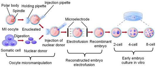
As shown in Figure 1, we discovered three high-risk nodes in the embryo engineering technology process that have the greatest impact on the development of oocytes and embryos, namely, oocyte micromanipulation, oocyte electrical activation/reconstructed embryo electrofusion, and early embryo in vitro culture. In the whole process of embryo engineering technology, the survival rate of oocytes passing through these three critical nodes to develop smoothly to the next stage is low. Therefore, how to help oocytes pass through these high-risk nodes has become a key issue that needs to be resolved. At present, scientists have carried out much research on related aspects.
Critical nodes in the process of embryo engineering technology (take SCNT as an example).
This paper focuses on the development of embryo engineering technology. The second to fourth sections of this paper describe the work that scientists have done to date in terms of the three high-risk nodes mentioned above and explain how the application of new techniques can improve the efficiency of embryo engineering technology and the survival rate through these high-risk nodes. In conclusion, the fifth section summarizes the current research status and challenges of these three critical nodes and proposes the prospect of future development directions. The fifth section analyses the research status and existing bottlenecks of these three critical nodes and proposes corresponding solutions and prospects for future development directions.
2. Oocyte micromanipulation
First, in the process of embryo engineering technology, micromanipulation is the first hurdle that oocytes will confront. At present, the main micromanipulations on oocytes include: The sperm tail is trimmed and the sperm head is injected into the oocyte during ICSI; The nucleus of the oocyte is extracted and a new nucleus is injected during SCNT; One cell of the 4~8-cell stage embryo or the first/second polar body of the oocyte before or after fertilization is taken to detect whether the gene is defective during PGD. These micromanipulations on oocytes involve the modification and reorganization of the internal structure and material of the oocyte, such as performing a complex “surgery” on the oocyte, which is the most damaging step to the oocyte. It is also the most critical step in determining the survival rate. The accuracy of the manipulation part, the control of the extraction/injection quantity, and how to minimize the damage to the oocytes in the process of breaking through the zona pellucida are three critical problems that we must face. We summarize these issues as follows: targeted micromanipulation, minimally invasive micromanipulation and quantitative micromanipulation. From these three perspectives, researchers have carried out substantial work.
2.1 Targeted micromanipulation
Targeted micromanipulation is the precise manipulation of specific parts of the oocyte. To achieve this goal, it is first necessary to identify the internal structure of the oocyte through microscopic image identification technology to find the best operating position and operating angle, adjust the oocyte to the best position suitable for manipulation and fix it to facilitate the next manipulation.
2.1.1 Image identification in micromanipulation
The identification of the oocyte and the end-effector is the first problem that needs to be solved to realize targeted microinjection. The traditional method is to magnify the target area through a microscope, and then the observer visually finds and identifies the oocytes and end-effectors [14]. This method requires high-level practitioners and is inefficient. At present, the automatic identification of oocytes and end-effectors by computer vision has become the mainstream [15]. Generally, images are collected by a charge-coupled device (CCD) camera. After greyscale conversion, noise filtering and signal enhancement, the images are transmitted to the computer memory through an image acquisition card, which is then called and processed by an image processing algorithm, and finally, the identification of the target object (end-effector and oocyte) is completed.
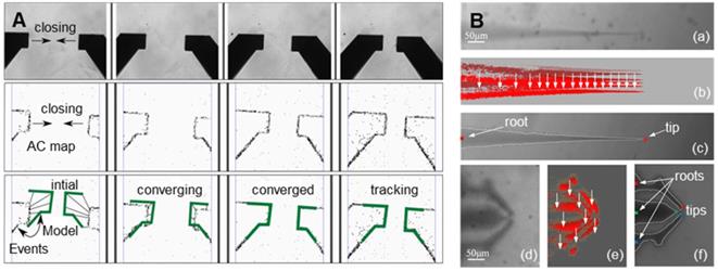
The image identification of the end-effector realizes the precise control of the end-effector by the computer and the mechanical arm [16,17]. Due to the characteristics of the end-effector and movement characteristics of oocyte micromanipulation, high-speed and high-precision identification and tracking of targets is the goal of the identification algorithm. Ni et al. [18] proposed an iterative nearest point algorithm to track the position of the microgripper. Figure 2A shows the principle of EICP tracking. The first row shows the gradual closing process of the fixture, the middle row is the cumulative graph of events, and the last row shows the edge tracking of the gripper by the EICP model. However, the implementation of this algorithm requires the use of additional dynamic vision sensors on the hardware, which is relatively complex in terms of system integration. Anis et al. [19,20] used template matching methods to track micromanipulators with obvious features. However, in many cases, micromanipulators do not have obvious features, and template matching has real-time problems in detection. Sun et al. [21] used a sum-of-squared-differences optical flow (SSD) algorithm to track the injection needle in oocyte injection, but SSD was effective only when there were no significant changes between successive frames of images. Liu et al. [22] developed an algorithm based on the motion history images (MHIs) and an active contour model to locate the tip of the end-effector. Figure 2B shows the recognition of the tips of micropipettes and microgrippers using this algorithm. Figures (a) - (c) depict the original image of the micropipette, corresponding MHI of the moving micropipette, and tip detection result based on active contour, respectively. Figures (d) - (f) show the original image of the microgripper, corresponding MHI of the moving microgripper, and tip detection result based on active contour. The algorithm can accurately locate the end-effector in the defocusing state or not in the image field, but the threshold in MHI detection must be selected appropriately to balance the algorithm failure rate and manipulation efficiency, and the selection of the threshold is sensitive to light. In addition, algorithms such as support vector machines [23] and Kalman filters [24] have also been used to detect or track objects in microscopic imaging systems. These algorithms have certain pertinences and great limitations.
Image recognition of the end-effector. (A) Track the position of the microgripper through an iterative closest point algorithm. Adapted with permission from [18]. (B) Recognize microinjection needles and microtweezers through algorithms based on motion history images (MHI) and active contour models. Adapted with permission from [18], copyright 2012 IEEE, and [22], copyright 2013 IEEE.
The image recognition of oocytes distinguishes the different organelles of oocytes to perform precise manipulations. The structure of oocytes is complex and includes dominant structures such as the zona pellucida, cell membrane, cytoplasm, and polar bodies, and recessive structures, such as the cytoskeleton, spindle, and mitochondria. Dominant structures can be observed directly under an optical microscope, while recessive structures can only be observed with the help of special techniques.
The recognition of oocyte contours mainly uses image segmentation technology and contour extraction technology. Image segmentation is usually performed before contour extraction to make the contour of the image more prominent [25, 26]. The basis of image segmentation is based on the grey level difference between the object and the background. The minimum value between the two peaks in the grey distribution histogram is selected as the best threshold to threshold the graph [27]. Since most suspended cells have a spherical or nearly spherical shape, after image segmentation is completed, the contour of the cell image can be extracted by the geometric figure extraction algorithm. Common edge detection algorithms include the Sobel algorithm [28, 29], Canny algorithm [30], Hough transform [31, 32], snake model [33], etc. Huang et al. [34] applied the Canny edge detection algorithm to automatically detect the contour of the chorion and cytoplasm of zebrafish oocytes and the edge of a microinjection needle in their experiment and adopted chord midpoint Hough transformation (CMHT) to improve the efficiency and accuracy of ellipse detection in the images. Figure 3A shows how the vision system captures and processes images. Among them, figure (a) is the original image of the zebrafish embryo, figure (b) and (c) are edge detection results of the original image, and the final figure (d) is the histogram of the zebrafish embryo radius.
Image recognition of different parts of oocytes. (A) Detection of the chorion and cytoplasm of zebrafish oocytes and the edge of the microinjection needle by the Canny algorithm. (B) Detection of the existence and direction of polar bodies through image processing. (C) The fusion images from polarized light microscopy imaging systems and the traditional optical inverted microscope imaging system and the edge information of the fusion image. Adapted with permission from [34], copyright 2009 IEEE, and [39], copyright 2017 IEEE, and [48], copyright 2013 IEEE.
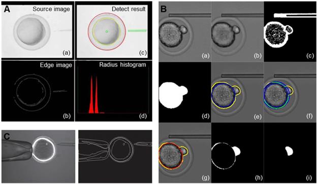
The image identification of the oocyte polar body is mainly used to rotate the oocyte to a proper posture to avoid the polar body during microinjection. Leung et al. [35] identified the polar bodies of mouse oocytes/embryos, first using morphological manipulations to obtain the general contours of the cytoplasm and the polar body, then fitting the contours of the cytoplasm, and finally using the differences between the two contours to obtain the polar body region. Sun et al. [36] proposed a new method to automatically locate the polar bodies. This method uses contour tracking to search for oocytes and then identifies polar bodies through the support vector machine (SVM) algorithm. Later, these authors proposed a polar body detection method based on machine learning [37], which used an improved histogram of gradient (HOG) algorithm to extract polar body image features to increase the success rate. At the same time, a position prediction method was proposed to reduce the search range of the polar body and improve the efficiency. In their latest study, these researchers proposed a framework based on deep learning to realize polar body detection in oocyte rotation [38]. The typical convolutional neural network for medical image segmentation is improved for polar body detection, especially for defocusing polar bodies and polar bodies of different sizes. In addition, these investigators designed a special image transformation method to simulate more oocyte rotation conditions, including oocyte and pole deformation, so that the deformed pole in oocyte rotation can be detected by this method. Wang et al. [39] realized automatic focusing on the pipette and oocytes and simultaneously introduced image processing technology, which could detect the presence and direction of the polar body when the oocyte was rotating at the tip of the pipette. As shown in Figure 3B, figure (a) is the original cropped image, figure (b) is the apply greyscale image opening, figure (c) is the Otsu's thresholding of (b) and Sobel edge detection of (a), figure (d) is the morphological filter and hole filling, figure (e) is the contour of the intracellular structure and its inscribed circle in yellow and blue lines, respectively, figure (f) is the overlapping part of the ring of the inscribed circle and the intracellular structure contour indicated in green, figure (g) is the ellipse fitting based on the overlapping part (the red ellipse is used to estimate the portion of cytoplasm), figure (h) is the estimated cytoplasm from (d) and figure (i) is the largest suitable blob is taken as the polar body after the binary image open operation. Mozafar et al. [40] developed a visual identification system for identifying oocytes and their polar bodies. The gradient-weighted Hough transform method is used to detect the position of the oocyte and its polar body to notify the automatic injection mechanism to avoid the polar body. In addition, considering the morphological differences between oocytes, they adopted a new elliptic fitting method to measure the size of oocytes and their polar bodies. The proposed algorithm is designed to be suitable for typical commercial inverted microscopes with different standards.
The purpose of image identification for oocyte spindles is to extract the nuclei of oocytes precisely and improve the success rate and efficiency of experiments. The traditional method is mainly to observe the spindle through the fluorescent probe method [41-43] or the polarized light imaging method [44-47]. The fluorescent probe method stains oocytes with dye and then observes the chromosomes of oocytes under a fluorescence microscope. However, fluorescent dyes have toxic side effects on oocytes, and excitation light close to ultraviolet light can damage the oocytes. Polarized light microscopy imaging systems can image the spindle of oocytes without injury, but they will lose much operating environment information, such as the precise location of the end-effector and oocyte texture. Huang et al. proposed a multicue image fusion method [48,49], which fused the images from polarization optical microscopy and traditional inverted optical microscopy, retaining their respective advantages. The fusion result is shown in Figure 3C; the fusion result is on the left, and the edge information of the fusion result is on the right. The fused image can clearly observe the spindle in the oocyte without losing the information of the operating environment.
2.1.2 The manipulation of the oocyte
After accurately identifying the internal structure of oocytes, the operating position and operating angle were determined. Since an ordinary optical microscope can only provide two-dimensional image information and the operating space is limited, the traditional way to move the end-effector to the right position is not suitable. However, it is a better choice to adjust the oocyte to the most suitable posture and then fix it through various techniques; this approach is called oocyte manipulation. In the process of oocyte micromanipulation, the techniques for adjusting oocyte posture can be classified into contact methods and noncontact methods. The contact methods mainly fix the oocytes through negative pressure holding or microtraps and then adjust the oocytes to a proper posture by operating tools. Noncontact methods involve changing the position and posture of oocytes through noncontact techniques such as microfluidics, dielectrophoresis, optical tweezers or magnetic fields and then fixing them. Table 1 summarizes the current common contact and noncontact oocyte operating and controlling methods.
Oocyte manipulation methods
| Manipulation methods | Advantage | Disadvantage | References | |
|---|---|---|---|---|
| Contact methods | Microcapillary negative pressure suction | Simple structure, easy to combine with existing micromanipulation systems | Requiring a high-precision source and can only fix one oocyte at a time | [50,51] |
| “Microtrap” device | Batch processing oocytes | Size of the microtrap will affect the fixing effect | [34,52] | |
| Combination of negative pressure suction and a “microtrap” | Batch processing oocytes with a good fixation effect | Complex structure | [53] | |
| Noncontact methods | Microfluidic | Less damage to oocytes | Complex manipulation and low efficiency | [35,54-58] |
| Dielectrophoresis | High-precision and fast response | The structure is complex and the electric field may affect other equipment | [59-64] | |
| Optical tweezers | Not limited by the operating space | Operating force is small, with potential heat damage to oocytes | [65-74] | |
| Magnetic field | High precision | The complex structure and magnetic field may affect the manipulation of other equipment | [75-79] |
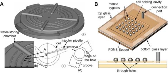
The traditional method is to attach a microcapillary to an air pump, which generates negative pressure to suction oocytes [50,51]. However, this method can only manipulate one oocyte at a time and requires high precision and stability of the air pump. The oocyte will be damaged if the suction force is too large. Many researchers have prepared devices that can fix oocytes in batches. Lu et al. [52] immobilized zebrafish embryos through rows of parallel V-shaped grooves made of gel at the bottom of a Petri dish in microinjection experiments, but this method has strict requirements on the direction of injection. As shown in Figure 4A, Huang et al. [34] used agarose gel to make a zebrafish embryo fixation device with an array of hemispherical grooves. Compared with the previous device, this device allows injection from any direction and is biocompatible. However, the size of the hemispherical groove will have a large effect on the experiment. As shown in Figure 4B, Sun et al. [53] designed a glass device with array round holes for batch fixation of oocytes. This device combines negative pressure suction and a microtrap and has a large air chamber, which can improve the stability of negative pressure suction and improve the survival rate of oocytes.
Contact cell fixation device. (A) The zebrafish embryo fixation device with arrayed hemispherical grooves. (B) The glass chip with arrayed round holes. Adapted with permission from [34], copyright 2009 IEEE, and [53], copyright 2009 Springer Nature.
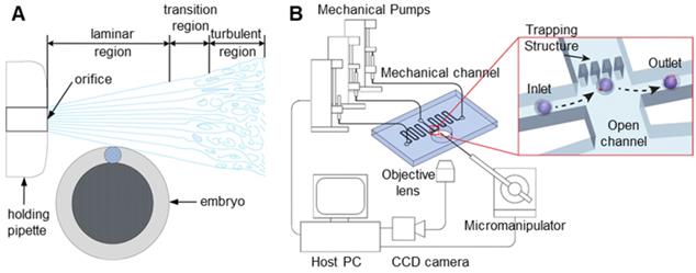
In noncontact oocyte manipulation technologies, microfluidics mainly uses microfluidic flow to generate forces acting on oocytes, thereby fixing oocytes or adjusting their poses [54-57]. This method does not require contact with oocytes and causes little damage to oocytes, but its process is complicated and inefficient. As shown in Figure 5A, when Sun et al. [35] analysed fluid flow, they found that fluid flow can generate a torque that makes the oocyte rotate. The fixed microcapillary can produce laminar and turbulent flow. The turbulence is chaotic, lacks stability and cannot be used. Laminar flow has smooth characteristics and is ideal for driving cells to rotate. Laminar and turbulent regions can be controlled by adjusting the flow rate of the fluid produced by the microcapillary. A lower flow rate leads to a larger laminar flow area. Therefore, oocyte rotation can be achieved by controlling the flow velocity of the fluid in the microcapillary. Shin et al. [58] designed a microfluidic platform to automate the process of oocyte capture and direction control through fluid dynamics and vision-based position control. The microfluidic channel and system configuration are shown in Figure 5B. A direction control algorithm based on the movement of oocytes in the microchannel is proposed. Visual tracking of the polar body is used to provide information about the embryo direction. The experimental results show that the embryo direction can be automatically controlled without manual intervention. Conventional microinjectors can access the device through the lumen so that fixed oocytes can be manipulated.
(A) Sun uses the torque generated by the fluid flow to rotate the cells. (B) A microfluidic platform used to achieve oocyte capture and direction control. Adapted with permission from [35], copyright 2012 IEEE, and [58], copyright 2013 IEEE.
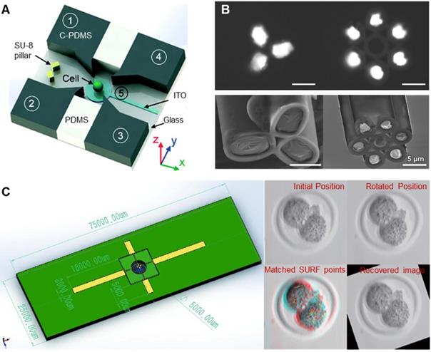
Dielectrophoresis (DEP) refers to the process in which oocytes are polarized in nonuniform electric fields and subjected to dielectrophoretic forces. Thus, oocytes can be controlled by adjusting electric field parameters to change the dielectrophoretic forces [62-64]. As shown in Figure 6A, Huang et al. [62] designed a dielectrophoretic chip consisting of four vertical carbon-black-nanoparticle-PDMS (C-PDMS) electrodes, an ITO electrode at the bottom, and a single cell trap/release module. The trap/release module allows a single cell to be hydrodynamically captured and then transferred to a rotating cavity formed by electrodes. The cell can be rotated in 3D by applying appropriate AC signals to the electrodes. As shown in Figure 6B, Yu et al. [63] prepared a capillary microneedle electrode based on liquid metal by injecting liquid metal gallium into a multitube glass capillary. By applying multifrequency, multiamplitude, multiphase AC electrical signals to the microelectrodes, three-dimensional dielectric electrophoresis traps and one-dimensional electrical rotation can be generated simultaneously, realizing 4D single-cell manipulation. As shown in Figure 6C, Huang et al. [64] connected an inverted microchip with four electrodes to a manipulator as robotic dielectric electrophoresis tweezers to drive the embryo lying on the petri dish for rotation. A vision-based algorithm was developed to obtain the position and direction of the embryo and provide feedback signals to achieve precision control of the embryo. Compared with the first two systems, this system can quickly process large numbers of cells in a contactless, low-cost, and flexible manner. Manipulating oocytes based on DEP can have a high accuracy and a fast response speed, but whether polarization in a nonuniform electric field will cause damage to oocytes has not been studied.
(A) Schematic diagram of a dielectrophoretic chip. (B) Scanning electron microscopy image of liquid metal-based capillary microneedle electrodes. (C) The effect of dielectrophoresis forceps and drive oocyte rotation. Adapted with permission from [62], copyright 2018 Royal Society of Chemistry, and [63], copyright 2018 John Wiley and Sons, and [64], copyright 2020 IEEE.
Optical tweezers provide a new method for cellular manipulation [65-67]. Optical tweezers capture and move objects using the force exerted by a strongly focused beam of light. The intensity gradient in the converging beam draws small particles to the focus, and particles can be captured in three dimensions near the focus. We can move and rotate cells by changing the focus of the laser beam. Zhou et al. [68] summarized the working principles and unique functions of various optical tweezers as well as their applications in biology. However, the manipulation force provided by optical tweezers is relatively small, which is slightly insufficient in manipulating oocytes. Cells and biological tissues have a certain ability to absorb light, and using optical tweezers to manipulate cells may cause potential heat damage. The magnetic field method attaches magnetic particles on the cell surface and then drives the cell to move or rotate by driving the magnetic particles on them [69-73]. These two methods have been successfully applied to the manipulation of nanoparticles and somatic cells but have not yet been successfully applied to oocyte manipulation. However, these two methods have the potential to manipulate oocytes and may be further developed by researchers.
2.2 Minimally invasive micromanipulation
The thick zona pellucida outside the oocyte becomes the barrier we need to break through after determining the precise operating position of the oocyte and adjusting the posture of the oocyte to meet the end-effector. Manual manipulation mainly reduces the damage to oocytes through thinner microcapillary and higher puncture speed. However, if the needle is too thin, it will be too soft and will affect the suction or injection of substance. Therefore, the diameter of the needle tip cannot be reduced indefinitely. To reduce the damage to oocytes and evaluate the damage to oocytes in the process of membrane puncturing, many new technologies have been applied. Researchers first believe that the force received by oocytes during membrane puncture is an important factor for oocyte injury and hope to measure and control the micropuncture force. At the same time, some advanced membrane puncture technologies have also been used to improve oocyte micromanipulation devices.
2.2.1 Measurement of micropuncture force
In the oocyte membrane puncturing experiment, the micropuncture force exerted on the oocyte is usually on the order of micronewtons. As shown in Table 2, the micropuncture force measurement methods are mainly divided into direct and indirect measurements [74,75]. The direct measurement method is mainly used to measure the film puncturing force through microforce sensors. There are many kinds of force sensors to measure the film puncturing force, such as piezoresistive force sensors, capacitive force sensors, piezoelectric force sensors and optical force sensors. Indirect measurement methods mainly include vision-based methods, calculation methods and actuator input methods.
Measurement of the micropuncture force
| Measurement methods | Advantage | Disadvantage | References | |
|---|---|---|---|---|
| Direct measurement | Piezoresistive force sensor | Simple structure, easy to combine with existing microinjection systems | High assembly precision and easily affected by environmental temperature changes | [76,77] |
| Capacitive force sensor | Large force measurement range and high accuracy, multi-axis force information can be measured, not affected by environmental temperature changes | Complex structure and high cost | [78-81] | |
| Piezoelectric force sensor | Large measurement range, high bandwidth, small size and high power density | Susceptible to ambient temperature change and charge leakage will lead to signal drift | [82-84] | |
| Optical force sensor | High sensitivity, anti-electromagnetic interference, no hysteresis, and no limitation of the operating space | Susceptible to light reflection or refraction, and has potential heat damage to cells | [85-87] | |
| Indirect measurement | Vision-based method | Not limited by operating space and without any damage to cells | Low precision | [88-90] |
| Calculation method | Can detect forces that are not easy to measure directly | Complex structure and low precision | [91,92] | |
| Actuator input method | Suitable for online measurement and control, without additional equipment | Poor precision | [93,94] |
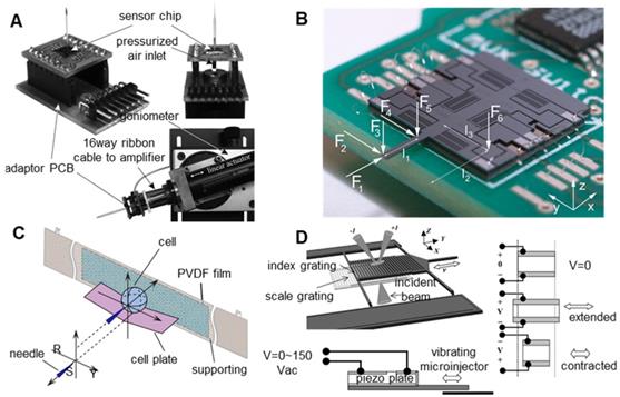
The resistance of the piezoresistive force sensor will change with the variation in the external force, and the size of the external force can be obtained by measuring the resistance [76,77]. Due to the simple structure, the resistive force sensor can be easily combined with the existing microinjection system, but it requires high assembly accuracy and is easily affected by environmental temperature changes. As shown in Figure 7A, Beutel et al. [77] integrated a silicon piezoresistive microforce sensor on the tail of a microcapillary to measure the injection force during microinjection. Thanks to the rapid development of microelectromechanical systems (MEMS) technology, a variety of capacitive force sensors based on MEMS technology [78-81] have been prepared. This sensor has advantages including low power, low noise, large range, and high sensitivity, can measure the force information of multiple axes and is not sensitive to environmental temperature changes. However, capacitive force sensors also have some limitations including complex structures, short lives, and a difficult integration with existing microinjection systems. As shown in Figure 7B, Beyeler et al. [81] designed a capacitive force sensor that can measure the force or moment of six axes and has a resolution of micronewtons and nanonewtons. The piezoelectric effect sensor is mainly prepared based on the piezoelectric effect of piezoelectric materials (piezoelectric ceramics (PZT) and polyvinylidene fluoride (PVDF)). [82-84]. Piezoelectric sensors have the advantages of a large force measurement range, a high bandwidth, a small size and a high power density, but they are also vulnerable to temperature changes and signal drift caused by charge leakage. Therefore, piezoelectric sensors are more suitable for dynamic force measurements but not for static force measurements. Figure 7C shows the injection force sensing scheme designed by Xie et al. [84]. The microforce sensor adopts a simple supported beam structure. A PVDF film is adhesively bonded to the back of the supporting beam. The cell plate is well placed on the beam such that the centre points of the beam, the PVDF film, and the cell coincide with each other. When the needle penetrates into the cell along the extension line of the RO, the process can be considered a quasi-static process. According to Newton's law, the cell penetration force equals the force applied on the PVDF film. Optical force sensors measure force based on changes in the intensity or phase of light signals [85-87]. The optical force sensor can measure the injection force without contact. The optical force sensor has the advantages of high sensitivity, anti-electromagnetic interference, good reproducibility, no hysteresis, and no limitation of the operating space. However, optical force sensors are easily affected by light reflection or refraction. Since cells absorb light energy, optical force sensors can facilitate potential thermal damage to cells. Using near-infrared light to form optical force sensors can reduce damage to cells. As shown in Figure 7D, Zhang et al. [87] integrated an optical MEMS force sensor on a vibrating microinjector, which consists of two vertically separated microgratings. In the experiment, a HeNe laser (633 nm/4 mW) was used to illuminate the grating. The injection force is determined by the relative displacement of the two gratings, which is determined by the intensity distribution of the diffraction orders.
Various sensors for measuring the injection force. (A) Piezoresistive force sensor. (B) Capacitive six-axis force sensor based on the MEMS process. (C) Microforce sensor based on piezoelectric material PVDF. (D) A micro-optical force sensor. Adapted with permission from [52], copyright 2012 IEEE, and [81], copyright 2009 IEEE, and [84], copyright 2009 SAGE Publications, and [87], copyright 2006 IEEE.
Among the indirect measurement methods, the vision-based method mainly uses microscopic image processing and an accurate oocyte mechanics model to determine the micropuncture force [88-90]. Force is usually calculated based on the deformation of visually tracked flexible objects (such as oocytes and end-effectors). The measured geometric information is processed by the force estimation algorithm to obtain the micropuncture force. This method is suitable for dynamic measurements, but due to the limitation of the oocyte mechanics model, the precision of the measurement results is not very high. The calculation method solves the unknown force through various force functions [91,92]. This method is suitable for detecting forces that are not easy to measure directly, but the structure of the instrument is complex. Others indirectly estimated the injection force through the input of the actuator [93,94]. This method is suitable for online measurement and control, but the precision is poor. In addition, there are many other indirect measurement methods. Because of the poor accuracy of indirect measurement methods, it will not be introduced in too much detail here.
2.2.2 Control of the micropuncture force
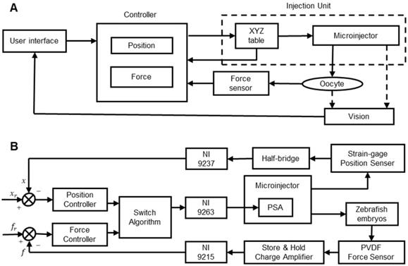
The control of the micropuncture force is very important in oocyte membrane puncturing experiments. If the micropuncture force is too small, then it will not be able to penetrate the zona pellucida and cell membrane of the oocyte. If the injection force is too large, then the oocyte may be hurt or even die. Therefore, achieving the precise control of the injection force has become the key to improving the success rate. Xie et al. [84] developed a cell injection method based on force control, which can adjust the penetration force according to the desired force trajectory. As shown in Figure 8A, the proposed force control framework includes two control loops. The inner loop is an impedance control used to specify the interaction between the microcapillary and the embryo. The outer loop is a force tracking nonlinear controller using feedback linearization technology. With the proposed force control method, the puncture force can be clearly adjusted during the embryo injection process to follow the desired force trajectory. Karimirad et al. [95] proposed a vision-based method to model a precision load cell with artificial neural networks. The proposed neural network model combined with the boundary detection algorithm can act as a load cell capable of measuring force with a range of µN to mN. The algorithm can trace and characterize embryo deformations by extracting geometric features called “pit angles” directly from images of the embryo micromanipulation process. The neural network was trained with the experimental data of zebrafish embryo micromanipulation, and the trained neural network was suitable for indentation of any other spherical elastic object. The results of this study can be used to measure forces during microinjection of biological cells, such as mouse oocytes/embryos, and are particularly suitable for situations requiring force feedback. Sun et al. [96] developed a static PVDF microforce sensor based on the inverse model method to detect the cell injection force and developed a fuzzy-PID feedback-based closed-loop control method to control the cell injection force. Experiments show that the system can track and control the injection force in cell micromanipulation, but the accuracy and stability need to be further improved. Wang et al. [97] designed a piezo-driven cell injection system that combines force and position control. The PVDF force sensor for detecting the micropuncture force and the strain gauge sensor for measuring the microcapillary relative position in real time are integrated into the system. As shown in Figure 8B, by introducing the weight coefficient method, the challenge of transient pulsation between force and position controller switching can be reduced. An adaptive sliding mode control method with parameter estimation is used to compensate for the hysteresis nonlinearity and disturbance of the piezoelectric actuator. The injection force is controlled by an incremental PID controller. The whole system is low cost, easy to install and easy to maintain.
(A) Schematic diagram of the cell injection system with inner loop impedance control and outer loop feedback control. (B) An injection system solution with position/force switch control. Adapted with permission from [84], copyright 2009 SAGE Publications, and [97], copyright 2017 IEEE.
2.2.3 Improvement of micropuncture technology
The conventional microinjector penetrates the zona pellucida and cell membrane of oocytes by mechanical squeezing. During the puncture process, a certain force and initial velocity must be given to the microcapillary tip [98, 99]. However, as the zona pellucida of oocytes is extremely tough, mechanical squeezing will cause large deformation of oocytes, which can severely damage or even kill oocytes. Subsequently, piezo-driven ultrasonic microinjectors based on the inverse piezoelectric effect were developed [100], but the piezoelectric actuator produced the axial vibration required for puncture and produced harmful lateral vibration. Excessive lateral vibrations will tear and kill the oocytes. Some researchers have added mercury or heavy oil to the tip of the microcapillary to attenuate the lateral vibration [101-102]. Although this method is effective, mercury and heavy oil will have toxic side effects on fragile oocytes. Other researchers used micromotors to rotate microcapillaries to reduce damage to oocytes [103], but the results were modest.
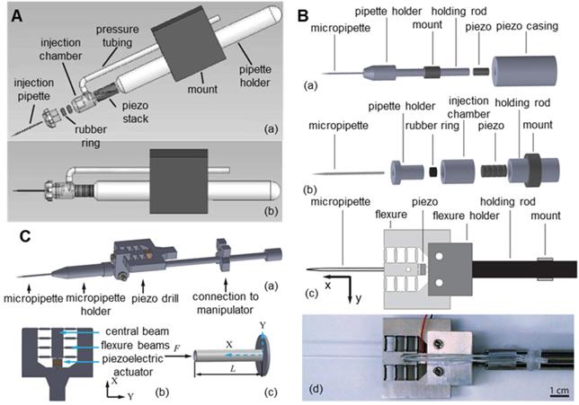
To reduce the lateral vibration of the piezoelectric ultrasonic microinjector, researchers began to improve its structure. As shown in Figure 9A, Huang et al. [104,105] proposed a novel design of a piezo-driven ultrasonic microinjector. By prepositioning the piezoceramics, the power of piezoelectric oscillations is concentrated on the pipette of the syringe, thus eliminating the vibration effect on other parts of the micromanipulator and reducing harmful lateral vibration. In the automatic cell injection experiment on zebrafish embryos (n=200), the microcapillary penetrated oocytes at low speed and with small deformation. The success rate was 96%, and the survival rate was 80.7%. As shown in Figure 9B, Johnson et al. [106] connected the piezoelectric ceramic and the microcapillary with a flexure mechanism on the basis of the piezoelectric ceramic to further reduce the lateral vibration. In the puncture experiment of mouse oocytes (n=45), the puncture success rate reached 100% and only caused a 3.4 µm deformation of the oocyte during the puncture process. As shown in Figure 9C, Dai et al. [107] installed the piezoelectric actuator next to the holder of the microcapillary by adopting the eccentric configuration of the piezoelectric actuator, which has the advantage of not affecting the installation of the standard microcapillary. At the same time, these authors also developed a technology to correlate filters and motion history images based on angular feature probability data to automatically detect the cell membrane rupture through piezoelectric drilling. This technology can automatically stop the piezoelectric vibration immediately after the microcapillary penetrates the oocyte membrane. Compared with manual stopping, the time delay between membrane puncture and the stopping of piezoelectric vibration was greatly reduced, thus improving the survival rate after oocyte puncture. In addition, many researchers have improved piezoelectric ultrasonic microinjectors and achieved good results.
Various improved piezoelectric ultrasonic microinjectors. (A) Microinjector with piezoelectric ceramic front. (B) Piezoelectric ultrasonic microinjector with a flexible mechanism. (C) Microinjector with piezoelectric actuator eccentric configuration. Adapted with permission from [104], copyright 2011 Spring Nature, and [106], copyright 2018 IEEE, and [107], copyright 2020 IEEE.
At present, a great deal of work has been carried out in the study of oocyte injury. However, in terms of reducing oocyte injury during microinjection, these previous studies still have deficiencies. First, research on oocyte injury has basically focused on the cell surface, such as the zona pellucida. However, there are a large number of skeletal structures inside the cell, and the injury of these structures cannot be ignored. At present, relevant studies have established a more detailed mechanical model of oocytes to study and evaluate the mechanism of injury to cell internal fine and cytoskeletal structure during microinjection. For example, Liu et al. [108] established a kinetic model based on dissipated particles to study the degree of oocyte damage during microinjection. The damage to oocytes was simulated by studying the number of broken molecular bonds in oocytes. The greater the number of broken chemical bonds is, the greater the damage degree of oocytes. By studying the damage mechanism of oocytes during microinjection, the optimal parameters of oocyte membrane breaking can be set, which will be the key research direction of minimally invasive oocyte micromanipulation in the future.
2.3 Quantitative micromanipulation
In micromanipulation, it is often required to implement material exchange inside or outside the oocyte through injection or extraction, which is mainly achieved by microcapillary connections with air or liquid pumps. When the microcapillary is inserted into the oocyte, the positive/negative pressure of the air pump is adjusted to push/suck material into/outside the oocytes through the microcapillary [109,110]. In the SCNT experiment, oocytes underwent extraction and injection of nuclei. Controlling the amount of extraction and injection is the key to the success of the experiment. In the ICSI experiment, a single sperm is injected into oocytes, and the control of the injection volume is not only related to the success of the experiment but also involves ethical issues. The microinjection quantity is at the picolitre level. To achieve high-precision quantitative microinjection, researchers have mainly conducted investigations from the following two directions: develop high-precision syringe pumps to actively improve the accuracy of suction and injection or detect and control the quantity in real time during the suction and injection process.
2.3.1 High-precision injection pump
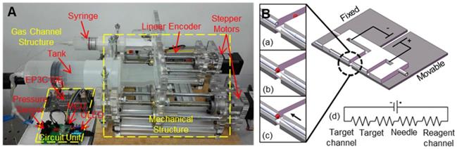
Microinjection experiments are usually carried out on commercial injection pumps using an air or oil pump as a pressure source. Commercial injection pumps include CellTram 4r Air and CellTram 4r Oil (Eppendorf), IM-400 and IM-400B (Narishige). However, due to the instability and accuracy of the pressure source, commercial pumps have some problems with respect to picolitre level injection, and the success rate varies greatly between different operators. Li et al. [111] developed a high-precision pressure-driven pump for quantitative injection of a subpicolitre. As shown in Figure 10A, by connecting the buffer tank to the gas channel, the new pump system has higher stability and resolution, various positive and negative pressures between -30 kPa and +150 kPa can be generated, the pressure control accuracy is less than 1 Pa, and the precision of the injection volume can reach 0.0022 pl. Noori et al. [112] realized the pumping of reagents through electroosmosis in an experiment. Electroosmosis is induced by applying a potential to the electrode embedded in the target and the reagent supply channel, as shown in Figure 10B. The advantage of using electroosmosis for reagent transport is that it eliminates the need for dedicated pumps and does not limit the size of the microcapillary, providing true scalability for the microcapillary. In addition, electroosmosis provides nonpulsed flow and precise electrical quantity control.
(A) High-precision pressure-driven pump for the quantitative injection of picolitre. (B) Electrical schematic diagram of the injection system based on electroosmosis. Adapted with permission from [111], copyright 2017 World Scientific Publishing Co, and [112], copyright 2009 Royal Society of Chemistry.
2.3.2 Detection and control of injection quantity in real time
Zhao et al. [113] proposed a new microcapillary aspiration method based on a common pneumatic microinjection system. This method is the first to use the equilibrium pressure model to quantify the effect of the capillary effect on suction or injection pressure. The method has the ability to quantify suction pressure and detect the joint between oocytes and microcapillary tissue. Wang et al. [114] first considered the influence of intracellular pressure on the microinjection amount. The experiments showed that intracellular pressure may result in an error of up to 30% between the actual injection quantity and the set value. In this work, the relationship between intracellular pressure and injection quantity was analysed and modelled to compensate for the control of the injection quantity. The experiments showed that the difference between the expected set value and the actual injection quantity was less than 3% after the intracellular pressure was compensated. Liu [115] obtained the critical injection pressure of the microcapillary through theoretical analysis and experimental verification, which provided reference data for quantitative cell injection. Chow et al. [116] controlled the injection quantity in the experiment by controlling the injection pressure and the opening time of the pressure and found a linear relationship between the injection amount and the injection pressure and a linear relationship between the injection amount and the injection time. This method does not require additional special equipment, but when the injection substance, injection target and microcapillary diameter change, the relationship among the injection pressure, pressure opening time and injection quantity needs to be recalculated again, which is very complicated. Sun et al. [117] proposed a method to characterize the injection volume of the robotic cell injection system by measuring the fluorescence intensity of the injected cells. The injection volume was determined by the changes in the fluorescence intensity of the cells before and after the injection. The injection volume can be controlled by adjusting the injection parameters (such as injection time and pressure) or the concentration of the substance to be injected by feeding back to the experiment. Huang et al. [118] designed a self-sensing microflow injection device based on piezoelectric ceramics. Based on the characteristics of the microdisplacement produced by the inverse piezoelectric effect, the injection volume was controlled by adjusting the size, frequency and time of the driving voltage. The self-induced displacement in the microinjection process can be obtained by using the normal piezoelectric effect, which realizes the integration of the sensor and actuator. The experiment showed that the device has good reliability and repeatability.
2.4 Conclusion for oocyte micromanipulation
The oocyte micromanipulation node is the most complicated node in the embryo engineering technology process and the node that causes the greatest damage to the oocyte. The quality of its completion directly affects the subsequent nodes. Therefore, much research has been focused on this node. At present, researchers have been trying to replace traditional manual operations with machine operations, and machine-assisted oocyte micromanipulation has been developing towards a targeted, minimally invasive, and quantitative direction. The application of the automatic identification and positioning technology of oocytes and end-effectors has greatly improved the degree of the automation of oocyte microinjection. The application of various contact and noncontact control methods has realized the control of oocytes with precise posture adjustment and fixation. The emergence of piezoelectric ultrasonic microscopic rupture technology makes it possible to complete the rupture of oocytes with minor damage to the oocytes. The application of various microinjection force sensors and control technologies makes it possible that the injection force is known and controllable. The development of high-precision syringe pumps and the closed-loop control technology of injection dose allow the exchange of materials inside and outside the oocytes to achieve nanoliter-level precision. These technologies use the machine's high sensitivity, high precision, and high stability to compensate for the lack of manual operation stability to improve the efficiency and success rate of micromanipulation. Although these technologies have shown certain advantages in terms of the degree of automation, in terms of the core index success rate, the results of machined micromanipulations have not shown much advantage over manual operations. The addition of various complex advanced technologies also increases the complexity of the system and increases the difficulty of operation for actual operators. This is also the inherent reason why machine-assisted micromanipulation technology still cannot replace manual operation and cannot be widely promoted and applied. Therefore, how to demonstrate the technical advantages of machine-assisted micromanipulation technology in the core index success rate will be a problem that we need to seriously think about and solve.
3. Oocyte electrical activation/reconstructed embryo electrofusion
In the process of embryo engineering technology, oocyte electrical activation/reconstructed embryo electrofusion is the second critical node that oocytes will confront. Various bioelectrical signals play an important role in the natural development of oocytes. Bioelectric stimulation can change the oocyte zona pellucida and the movement of ions in the solution to achieve various effects. Electrical stimulation is also a common method in various stages of oocyte micromanipulation. For example, during natural fertilization, oocyte activation is accomplished by sperm entry and induced calcium oscillation. In the process of parthenogenetic activation (PA) and ICSI, the artificially assisted activation of oocytes is essential. Presently known artificially assisted activation methods include mechanical stimulation [119, 120], chemical activation (enzymes [121], calcium ionophores [122, 123], ethanol [124, 125], etc.), and electrical activation [126, 127]. The unique advantages of electrical stimulation lie in that the parameters are easier to accurately control, the manipulation is simple, and there is no chemical toxicity. In addition, during SCNT, the fusion of oocytes and somatic cells is also accomplished by electrofusion.
3.1 Principles of electrical activation/electrofusion
Electrical stimulation techniques related to oocytes are mainly divided into electrical activation and electrofusion. Electrical activation means that the oocyte membrane is stimulated by a high-voltage DC pulse, and calcium ions flow into the oocyte as a second messenger through ion channels on the cell membrane, causing changes in the chemical substances in the oocyte, that is, stimulating the endoplasmic reticulum in the oocyte. The stored calcium pool is released, thereby increasing the concentration of Ca2+. On the one hand, the increased Ca2+ content destroys the existing cytostatic factor (CSF), thereby reducing the activity of the maturation promoting factor (MPF). On the other hand, increased Ca2+ causes the degradation of cyclin sensitive to Ca2+, initiates the activation of oocytes, and prompts oocytes to leave the MⅡ phase to complete embryonic development after meiosis. Electrofusion refers to the use of electrical pulses to create recoverable micropores in the recipient cell and donor cell in the fusion solution so that the two cell membranes fuse with each other. If the electric pulse is too large, then the micropores in the cell membrane will not be repaired. Thus, an appropriate electric pulse can make the cell membranes fuse, and the cytoplasm of the cells can facilitate communication and finally merge into one cell. Both electrical activation and electrofusion are the principles for establishing electroporation. In essence, the phospholipid bilayer structure of the cell membrane changes under the stimulation of electrical pulses. Electroporation refers to the generation of micropores in the cell membrane under the action of a high-intensity electric field, which improves the permeability of the cell membrane [128,129]. The micropores produced in the cell membrane allow substances in the culture medium to enter the cells, and many manipulations of oocytes are based on this theory [130].
When calculating the membrane potential difference, the cell membrane is regarded as an insulator, and the cytoplasm inside the cell and the suspension outside the cell are both regarded as electrolyte solutions. Under the action of an external electric field, both the cytoplasm and the cell suspension are polarized, and a membrane is produced. The potential difference Vm is given by formula (3-1):
(3-1),
where Eext is the applied electric field intensity, θ is the angle between the radial direction at an arbitrary point on the membrane and the electric field direction, and τ is the relaxation time constant of the dielectric membrane. When the frequency of the applied alternating electric field is low enough, we assume ωτ << 1, or when the applied electric field is a direct current (DC) electric field, formula (3-1) can be simplified to formula (3-2):
(3-2)
With two cellular extremum points, θ = 0° or 180°, the membrane potential difference induced by the applied electric field is further simplified as Eq. (3-3):
(3-3)
The potential difference is the largest at these two points. The induced membrane potential increases with increasing applied electric field intensity. In cell electroporation, the cell membrane will be perforated when the intensity reaches a special value: V = Vcr. Under this condition, the induced membrane potential Vcr is called the critical membrane potential, while the applied electric field Ecr is called the critical applied electric field. When the intensity of the applied electric field is higher than Ecr, the cell membrane begins to perforate. The higher the applied electric field intensity is, more or larger holes occur on the membrane. However, if the applied electric field is too strong, cell perforation becomes irreversible, and cells can be permanently damaged.
The above is the theoretical basis of cell electroporation, but the actual situation is much more complicated than this. Virtually all cells are not ideal spheres, different cells vary in size and shape, and the composition of their membranes and media varies. Therefore, when performing cell electroporation experiments, the theoretically calculated values are only for reference, and the best parameters are obtained through continuous experiments. Since cells have a strong ability to repair themselves, they can withstand large pulse amplitudes. Scientists have found that even low amplitude pulses can cause electroporation, but stronger amplitude pulses can achieve higher electroporation efficiency. The lower limit of the pulse width must be longer than the charging time of the membrane and the elastic recovery time of the membrane to keep the pores open. There is a complementary relationship between the pulse width and amplitude. To reduce the pulse amplitude, the pulse width needs to be widened to compensate; the efficiency of perforation is often proportional to the product of the pulse amplitude and the width. The most commonly used pulse waveforms are DC square wave pulses and exponentially decayed resistance-capacitance (RC) pulses. If the electrical pulse can maintain the membrane pores open for a period of time with a lower voltage after breaking through the cell membrane, then it will help improve the efficiency of cell electroporation. Therefore, RC pulses are often more effective than DC pulses of the same amplitude. In addition, increasing the number of pulses can obviously increase the efficiency of cell electroporation, but the death rate of cells also increases.
3.2 Application of electric activation/electrofusion
Researchers have used electrical stimulation to activate oocytes when studying PA and have carried out experimental exploration on many organisms, such as pigs [131-134], cows [135], and mice [136]. The specific research contents and conclusions are summarized in Table 3. By analysing the experimental data of previous researchers, we found that when parthenogenetic activation of oocytes is carried out, the effect of electrical activation (EA) is obviously better than that of chemical activation (CA) and mechanical activation (MA), and the combination of EA and CA can obtain a better effect.
Application of electrical activation in parthenogenesis
| Research objects | Research contents | Effects and conclusions | References |
|---|---|---|---|
| Pig | To study the influence of the number, frequency and interval of electrical stimulation pulses on the parthenogenesis of oocytes. | Neither the pulse frequency nor the pulse interval affects the rate of pronucleus formation. Multiple electrical pulse stimulation can achieve a faster development speed and a higher cleavage rate, the optimal electrical stimulation parameters: three DC pulses of 1.0 kV/cm for 50 μs, 5 min apart. | [131] |
| Study of the parthenogenesis of a pig comparing the EA and CA. | The cleavage rate of the EA was higher than that of the CA. The optimal electrical stimulation parameters: three DC pulses of 1.0 kV/cm for 50 μs. | [132, 133] | |
| Study of the parthenogenesis of a pig using a combination of EA and CA. | The electrically activated pig oocytes can obtain a higher blastocyst formation rate by anisomycin. The optimal electrical stimulation parameters: a direct current pulse of 1.5 kV/cm for 60 μs. | [134] | |
| Cow | Study of bovine parthenogenesis, using a combination of the EA and CA. | The optimal electrical stimulation parameters: two DC pluses of 1.75 kV/cm for 30 μs. The activated oocytes are treated with 6-dimethylaminopurine (6-DMAP). The cleavage rate can be comparable to IVF. | [135] |
| Mouse | Study of the parthenogenesis of mouse comparing the EA and CA. | Mouse oocytes could develop into blastocysts after EA or CA, but the formation rate and mass of the blastocysts after EA were significantly higher than that after CA, and the combined use of activators had no further positive effect on the development before implantation. | [136] |
Electrical stimulation is also widely used in ICSI to stimulate oocytes. Experimental studies have been conducted on many animals, such as rabbits [137, 138], pigs [139], and humans [140-142]. The specific research content and conclusions are summarized in Table 4. By analysing the experimental data of previous scientific researchers, we found that electrical activation can significantly increase the fertilization rate and cleavage rate of oocytes after ICSI, and the electrical activation of oocytes can be applied before or after ICSI.
Application of electrical activation in ICSI
| Research objects | Research contents | Effects and conclusions | References |
|---|---|---|---|
| Rabbit | Electrical stimulation was performed on rabbit oocytes 10 minutes before ICSI. | Electrically stimulated oocytes had a higher rate of activation and subsequent development (implantation rate, pregnancy rate, live birth rate). The optimal electrical stimulation parameters: a single pulse of 1.25 kV/cm for 100 µs. | [137] |
| The effect of electrical stimulation at different periods on the ICSI of rabbit oocytes was studied. | Rabbit oocytes that receive electrical stimulation before ICSI will have a higher rate of blastocyst development. The optimal electrical stimulation parameters: a single DC pulse of 2.5 kV/cm for 25 μs before ICSI. | [138] | |
| Pig | The effect of electrical activation on the ICSI of porcine oocytes was studied. | The cleavage rate and blastocyst development rate of the electrically activated group were significantly higher than the IVF group and the non-activated ICSI group, the optimal electrical stimulation parameters: a single DC pulse of 1.26kV/cm for 30 s, 30 min after ICSI. | [139] |
| Human | Electrical stimulation of unfertilized oocytes 24 hours after the ICSI. | Oocytes after electric stimulation can be normally fertilized and complete early embryo development, and repeated electric stimulation can significantly improve subsequent embryo development. The parameters of electric stimulation: 1.35∼1.5 kV/cm, 40∼60 μs. | [140] |
| Divide a large number of oocytes after the ICSI into two groups. One group receives electrical stimulation, and the other group serves as a control group without electrical stimulation. | The fertilization rate of the electrical stimulation group was significantly higher than that of the control group, and the degeneration rate of oocytes in the two groups was similar. The electrical stimulation parameters: a double-square DC pulse of 2.6∼2.8 kV/cm for 50 μs. | [141] | |
| The man suffered from round-head spermatozoa, and the oocytes cannot be fertilized after the ICSI. Electrical stimulation was applied to the oocytes 30 minutes after the ICSI. | The oocytes after electrical stimulation can be fertilized normally and develop to 4-8 cells, and then transplanted into the female uterus, and finally a healthy baby is successfully produced. The electrical stimulation parameters: a single DC pulse of 0.75 kV/cm for 50 μs. | [142] |
In SCNT, the fusion of somatic cells and enucleated oocytes usually uses electrofusion. Experimental studies have been conducted on many animals, such as pigs [143-154], cattle [146-150], goats [151, 152], and mice [153-155]. The specific research content and conclusions are summarized in Table 5. By analysing the experimental conclusions in Table 5, we found that appropriate chemical treatment of oocytes after electrofusion can improve the success rate of fusion. Generally, the electric field intensity required for electrical activation of oocytes should be lower than the electric field intensity required for electrofusion. However, when analysing the experimental data in Table 4 and Table 5, we found that this conclusion was not obvious, which may be due to the various oocytes used in the experiment, the composition of the culture medium, and the electric activation/electrofusion device being different.
Application of electrofusion in SCNT
| Research objects | Research contents | Effects and conclusions | References |
|---|---|---|---|
| Pig | Analyse the effects of the mature age and activation conditions of oocytes on the SCNT of pig oocytes. | The longer the oocytes were cultured, the higher the maturation rate. Additionally, the oocytes were more easily activated. The combined treatment of additional electrical stimulation and 6-DMAP after electrofusion can effectively improve the blastocyst formation rate. The electrofusion parameters: a single DC pulse of 1.5 kV/cm for 30 μs. | [143] |
| When studying the SCNT of pig oocytes, different electrofusion pulses were used, and the fusion was divided into 3 groups for processing. | The optimal electrofusion parameters: a single pulse of 1.1 kV/cm for 30 μs. The fused oocytes treated with cytochalasin B had a higher blastocyst formation rate. | [144] | |
| The effects of different electrofusion parameters on the manual cloning of pig oocytes were studied. | The optimal electrofusion parameters: a single pulse of 1.0 kV/cm for 9 μs. | [145] | |
| Cattle | Influence of different activation times on embryonic development after electrofusion. | The blastocyst development rate of reconstructed oocytes activated 3∼5 h after electrofusion was significantly higher than that of reconstructed oocytes activated immediately after electrofusion. The electrofusion parameters: a single DC pulse of 1.8 kV/cm for 20 μs. | [146, 147] |
| The effects of different electrofusion parameters and different shapes of somatic cells on embryonic development were studied. | The round smooth somatic cells are better than the prototype rough somatic cells. Donor cells with a diameter of 15~25 μm are better than others. The optimal electrofusion parameters: two DC pulses of 2.5 kV/cm for 10 μs. | [148] | |
| The effects of different electrofusion parameters on buffalo oocytes cloned by handmade cloning were studied. | The optimal electrofusion parameters: a single pulse of 3.36 kV/cm for 4 μs. | [149,150] | |
| Goat | Electrofusion oocytes of a goat. | The treatment of mammary gland epithelial cells with 100 mg/ml phytohemagglutinin before fusion can improve the fusion rate between the mammary gland epithelial cells and oocytes. The optimal electrical stimulation parameters: two DC pulses of 2.2 kV/cm for 10 μs. | [151] |
| The effects of different electrofusion parameters on the oocytes of cloning goats were studied. | The optimal electrofusion parameters: a double electrical pulse of 2.2 kV/cm for 10 μs. | [152] | |
| Mouse | Effects of unipolar pulses (UPs) and bipolar pulses (BPs) on the electrofusion of mouse SCNT embryos. | The experimental results showed that the bipolar pulse could effectively reduce the death of the embryos, and the electrofusion rate of the BPs was three times that of the UPs. | [153] |
| Electrofusion of 2-cell embryos to obtain single-cell tetraploid embryos. | The optimal electrical stimulation parameters: a single pulse of 3.5 kV/cm for 35 μs. | [154] | |
| Human-mouse heterogeneous hybridoma cells were produced based on cell electrofusion technology, and the effect of electric field direction on fusion was studied. | The fusion yield can be increased by firing pulses at the cells in both vertical directions. | [155] |
3.3 Electrical activation/electrofusion device
Traditional cell electrofusion systems use a fusion chamber with two parallel plate electrodes for electrofusion. The distance between two parallel plate electrodes is 1~10 mm, and the fusion electric field is generally ~kV/cm, which makes the voltage applied to the parallel plate electrodes reach hundreds to thousands of volts. Due to the surface tension of the liquid and the electrochemical reaction between the electrode and the buffer solution to produce bubbles, the electric field distribution in the electrofusion chamber is not uniform. In addition, the posture of the cells between the parallel plate electrodes is difficult to unify, causing fluctuations in the effect of electrical stimulation/electrofusion. Due to the limitations of traditional electrofusion systems, the effect of electrical stimulation/electrofusion on cells is very rough. Even the same device, the same batch of oocytes, and the same electrical parameters have different effects. Therefore, the miniaturization and refinement of oocyte electrical stimulation/electrofusion devices is an inevitable trend.
Liu et al. [156] analysed the effects of the electrofusion of goat SCNT embryos using electrodes of different shapes. As shown in Figure 11, the experiment used three kinds of microelectrodes: 15 μm tip-end, 100 μm frustum-end and 200 μm parallel microelectrodes. These microelectrodes were combined into four groups for the experiment: tip-end plus tip-end (TT), tip-end plus frustum-end (TF), frustum-end plus frustum-end (FF) and parallel microelectrodes (PM). In the four schemes, the interface between the nuclear donor and oocyte was perpendicular to the electric field. When the electrodes did not apply pressure to the reconstruction configuration, the fusion rate of the four groups was not significantly different; all were approximately 74%. When pressure was applied, the TT group showed a higher fusion rate (94.9%) and a lower degradation rate (2.1%). Compared with traditional electrode chamber fusion, electrofusion with pressure applied to the tip needle microelectrode is a better SCNT electrofusion scheme.
Schematic diagram of four electrofusion schemes. (a) Tip-end plus tip-end (TT); (b) tip-end plus frustum-end (TF); (c) frustum-end plus frustum-end (FF); (d) parallel microelectrodes (PM). Adapted with permission from [156], copyright 2007 Elsevier.
At the same time, under the premise of ensuring the success rate of oocyte electrical activation/electrofusion, microfluidic chips have inherent advantages in improving the efficiency of electrical activation/electrofusion. Although no related research on oocyte electrical activation/fusion chips has been reported, there are indeed many studies on microfluidic electrofusion chips for somatic cells, which can be referenced for future development of high-precision oocyte electrical stimulation chips. Researchers first found that cell pairing can be achieved by using dielectrophoresis force. A kind of cell electrofusion microfluidic chip with interdigitated microelectrodes was developed [157-159]. This microfluidic chip uses an alternating current to achieve cell pairing during manipulation and then direct current pulses to complete cell fusion. As shown in Figure 12A, Guillaume et al. [157] fabricated a microfluidic electrofusion device with a high-aspect-ratio microelectrode array. A 250 μm thick silicon electrode was bonded to a glass substrate by photolithography. The electrode was covered with a glass substrate coated with PDMS. The electrode spacing varied from 30 μm to 500 μm. The liposome cells were sequestered and paired with an alternating current of 0.1-0.2 kV/cm and 300 kHz. Then, 5 to 6 DC pulses of 5-10 kV/cm were applied for electrofusion. Cao et al. [158] produced a microfluidic chip with a similar structure for the electrofusion of plant protoplasts. As shown in Figure 12B, the microfluidic chip has 6 microchambers and a total of 1368 pairs of high-aspect-ratio silicon microelectrodes. The microchannels were 20 μm deep and 80 μm wide, and the electrode spacing was 50-100 μm, with increments of 10 μm. In the experiment, a 1.2 kV/cm, 2 MHz alternating current was used to pair the plant protoplasts; several 4 kV/cm, 20-50 μs direct current pulses were used for electrofusion. Hu et al. [159] used flexible printed circuit board (FPCB) technology to produce a new type of flexible cell electrofusion chip. As shown in Figure 12C, 2.2×10⁴ microelectrodes were integrated on the chip, which can perform cell electrofusion in large quantities. Human embryonic kidney cells (HEK-293) were paired under a 6 V, 1 MHz alternating current, and electrofusion was performed under 3 to 5 direct current pulses of 35 V for 50 μs.
Various electrofusion chips with interdigitated electrodes. (A) A schematic diagram of a microfluidic chip with a high-aspect-ratio microelectrode array. (B) An electrofusion chip with 1368 pairs of silicon microelectrodes. (C) A schematic diagram of the flexible electrofusion chip. unit: µm. Adapted with permission from [157], copyright 2004 Spring Nature, and [158], copyright 2008 Springer Nature, and [159], copyright 2009 Elsevier.
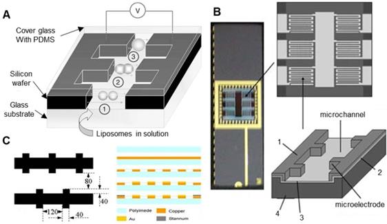
Compared with traditional electrofusion systems, microfluidic chips containing interdigitated microelectrode arrays have the advantages of a low voltage, a simple structure, and a high throughput. However, when using the dielectrophoretic force generated by alternating current to pair the cells, the number of paired cells cannot be controlled, and the cells are easily trapped in the nonelectrofusion zone between the two adjacent electrodes, which greatly reduces the pairing efficiency of the cells. Therefore, it is a better choice to use microstructures in microfluidic chips for cell pairing. Clow et al. [160] designed a double-layer microfluidic chip that integrates automatic cell positioning and cell electrofusion. As shown in Figure 13A, interdigital titanium electrodes with a thickness of 300 μm, a width of 250 μm, and a pitch of 250 μm were prepared on a borosilicate glass substrate. The electrode was coated with an electrically insulating photosensitive epoxy polymer (SU-8) film with a thickness of 4 or 22 µm. Micropits with diameters of 10-80 µm were made above the electrode. During the experiment, it was necessary to manually load the donor somatic cells and the recipient oocytes, draw the cells into the micropits through DEP to achieve pairing, and then apply high-voltage direct current pulses for electrofusion. The device cleverly introduces the micropit structure onto the microfluidic electrofusion chip, which effectively improves the success rate of cell pairing. However, DEP is still needed to fix cells, and the manual loading of cells undoubtedly increases the cumbersomeness of the experiment and reduces the efficiency. Skelley et al. [161] fabricated a microfluidic chip with thousands of microtraps made of PDMS arranged on a glass substrate. As shown in Figure 13B, the microtraps used to capture cells consist of a larger frontal capture ring (14 μm tall, 18 μm wide, 25-40 μm deep), a smaller dorsal capture ring (14 μm tall, 10 μm wide, 5 μm deep), and a support ring (7.5 μm wide, 35-50 μm long, 6-8 μm tall). In the experiment, a single cell A (green fluorescence) was first captured with a smaller backside capture cup. Once the array was saturated, cell A was transferred directly “down” to the relatively large capture cup. Finally, cell B (red fluorescence) was loaded. Cell B was captured by the larger capture ring in front and paired with cell A, with a success rate of up to 70%. This design makes clever use of hydrodynamics and specially designed microtraps to capture and pair cells. Robinson, T et al. [162] manufactured a microfluidic chip that could detach giant unilamellar vesicles (GUVs) of different diameters and perform electrofusion. As shown in Figure 13C, the chip contains a three-layer structure: a circular ring valve is integrated on the pressure control layer, a PDMS trap for capturing target cells is integrated in the fluid layer, and a patterned electrode is integrated on the glass base. GUVs with diameters much larger than 20 μm (the size of the trap passage) will not enter the trap. GUVs with diameters less than 8 μm will escape through a gap in the trap, allowing them to capture target-sized GUVs and pair them up. After all traps are captured and paired, the ring valve in each chamber can be hydraulically driven to isolate each trap to prevent GUVs from being affected by fluid shear. Finally, the electrofusion of GUVs can be completed by the output of a DC pulse through the microelectrode. Sugahara, K et al. [163] also produced a microfluidic chip that can be used for electrofusion GUVs. As shown in Figure 13D, the chip structure is very simple and was prepared from polydimethylsiloxane (PDMS) using standard soft lithography. One side of the snake-like pathway in the centre of the chip is designed to trap cells, and the chip is flanked by electrodes. The GUV suspension was injected into the chip with a syringe pump at a flow rate of 400 nL/min. GUVs were captured when they flow through the trap on the side of the channel. The trap can capture two GUVs and complete the pairing. The subsequent GUVs will follow the bypass channel and continue to flow until caught by the next trap. After the pairing is completed, the GUVs are electrically fused with DC pulse input through the electrodes. However, it should be noted that neither the microfluidic fusion chip with an interdigitated electrode nor the microfluidic fusion chip with a “microtrap” has been successfully applied to oocytes. In the future, a microfluidic electrofusion chip more suitable for oocytes may be developed.
(A) A double-layer microfluidic chip integrating automatic cell positioning and cell electrofusion. (B) A microfluidic chip integrates thousands of microtraps made of PDMS and its working steps. (C) A microfluidic chip can separate cells of different diameters and perform electrofusion and its working schematic diagram. (D) A microfluidic chip for electrofusion of GUVs and its working diagram. Adapted with permission from [160], copyright 2010 Spring Nature, and [161], copyright 2009 Spring Nature, and [162], copyright 2014 Royal Society of Chemistry, and [163], copyright 2020 Elsevier.
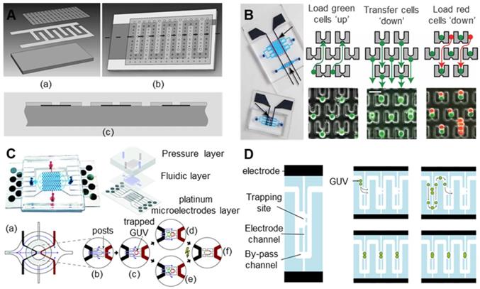
3.4 Conclusion for oocyte electrical activation/reconstructed embryo electrofusion
The oocyte electrical activation/reconstructed embryo electrofusion node is the weakest part of the embryo engineering technology process. Both electrical stimulation strategies and devices need to be improved. To date, much research work has been performed by researchers with biological backgrounds, focusing on adjusting various “optimal” electrical stimulation parameters to obtain a high activation rate/fusion rate. However, in many studies, only irregular conclusions have been obtained regarding the optimization parameters under the existing crude electrical stimulation device. This is also the underlying reason why the “optimal electrical stimulation parameters” obtained by relevant studies shown in Tables 4 to 6 of section 3.2 are totally different. Therefore, to truly determine the law of electrical activation/electrofusion parameters, the miniaturization and refinement of experimental devices is an inevitable trend. To date, substantial research and application in somatic cell electrofusion with precision electrical stimulation technology based on microfluidic chip technology has been carried out. This technology has shown good technical advantages and will definitely be the future development trend for oocyte electrical stimulation technology.
4. Early embryo in vitro culture
In the process of oocyte micromanipulation, the in vitro culture of early embryos is the third key node that determines the ultimate success rate. In the natural development process, the nutrition of the early embryo comes from the secretion of the mother's oviduct and uterine cavity. Its cellular activities (division, gene expression, and metabolism) are affected by factors produced by the environment, the embryo itself, and the cells of the reproductive tract. With the continuous development of biotechnology, we can bypass the fallopian tube and transfer embryos that have developed to the blastocyst stage to the uterus for further development through in vitro culture. The development process of embryo culture technology in vitro essentially involves constantly approaching the natural embryonic development process, simulating the natural environment of embryo development and meeting changing nutritional needs during embryo development. Chemical and physical factors have been proven to be a prerequisite for improving the culture environment of preimplantation embryos and are the basis for improving the rate and survival of blastocysts. At the same time, the microenvironment and macroenvironment in which the embryo is cultured in vitro also play a vital role in the development of the embryo. This part starts with analysing the reproductive mechanism and influencing factors of early embryos and deeply analyses the complex environment of early embryo development. Then, from the perspective of engineering technology, the research progress of in vitro embryo culture technology was systematically introduced.
4.1 Developmental mechanism and influencing factors of early embryos
4.1.1 Developmental mechanism of early embryos
The reproductive mechanism is a complicated problem of the interaction between fluid and structure. The sperm and oocyte meet to form a fertilized ovum, the fertilized ovum further develops to the cleavage and blastocyst stages, and the process of blastocyst transport to the uterus is completed in the fallopian tube. The fallopian tube plays an important role, and the whole reproductive process undergoes dynamic changes under mechanical and biochemical conditions [164]. Under an optical microscope, the fallopian tube mucosa is longitudinally folded, with a cubic or columnar epithelial layer. The epithelial cells in the epithelial layer are mainly divided into secretory cells and ciliated cells. The fallopian tube is not static but is dynamic, including muscle contraction and cilia beating [165]. Due to the intermittent contraction of the fallopian tube and uterus, the early embryo passes through the fallopian tube to reach the uterus and then uses the contraction of the myometrium from the cervix to the fundus to reach the implantation site at the bottom of the uterus [166]. The segmental muscle contraction of the fallopian tube wall not only drives the ovum to perform related exercises but also causes agitation of the material in the fallopian tube to ensure the mixing of gametes and embryos with the secretions of the fallopian tube [167]. The dynamic activity of the oviduct may directly change the surrounding environment of the embryo and promote the exchange of gas and biomolecules. The fallopian tube may play an important role in the mechanical action of the embryo. The conventional static culture mechanism cannot simulate the mechanical stimulation of the embryo, and simulating the microscopic environment of the structure of the fallopian tube may promote the development of the embryo.
4.1.2 Factors influencing early embryonic development
After understanding the reproductive mechanism of early embryos, researchers have attempted to create a culture environment close to living body development for early embryos when they are cultured in vitro. Chemical and physical factors must be considered when early embryos are cultured in vitro. Table 6 summarizes the effects of common chemical and physical factors on embryos.
The influence of chemical and physical factors on early embryos in the culture environment
| Factors | Effects and conclusions | References |
|---|---|---|
| Chemical Factors | ||
| Water | Water is an important component of the culture fluid. Nutrients and metabolites are absorbed and excreted by the oocytes by dissolving in water. The quality of water directly affects the effect of in vitro culture, and the small quantity of impurities can also affect the survival and development of oocytes. | [168] |
| Inorganic salt ion | In the process of embryo culture, inorganic salt ions play a role in regulating the osmotic pressure, maintaining the potential difference, and regulating the pH value in the medium. An ion concentration that is too high is not conducive to the development of the embryo. | [169] |
| Energy matter | Glucose, pyruvate, lactate, etc. are energy substances required for embryo cultures in vitro. Early embryos at different developmental stages require different energy substances. | [170] |
| Amino acid | Amino acids are the basic substances that make up protein, DNA, and RNA, as well as nutrients for early embryos. It can regulate the osmotic pressure, participate in trophoblast differentiation and the formation of basement membrane between endo and ectoderm, and promote the normal development of early embryos. | [171] |
| Vitamins | The effect of vitamins on embryonic development is to improve the energy metabolism-related enzyme activity, promote the embryo's absorption of glucose, and further promote the effect of early embryonic development in vitro. | [172.173] |
| PH value | To provide a good environment for embryos, early embryos need to simulate the acid-base environment in the living body when they are cultured in vitro. Most of the culture media rely on [HCO3—] and [H2CO3] as buffer materials to adjust the pH value between 7.2-7.4. | [174] |
| Physical Factors | ||
| Temperature | Changes in temperature directly affect the physiological metabolism of early embryos. Excessive temperature causes heat stress on embryos, which affects the decrease of key enzyme activities in the embryo and the abnormal expression of important survival genes, resulting in a decrease in the blastocyst development rate and embryo quality. A temperature that is too low will lead to the slow development of early embryos and even a developmental block. | [175] |
| Gas phase | The gas phase condition is one of the important factors of the microenvironment during the in vitro culture of early embryos. CO2 and O2 are two gas phase factors that have a greater impact on the embryo in vitro culture. CO2 can stabilize the pH, participate in the synthesis of the early embryonic protein and nucleic acid, and regulate metabolism. O2 supports the metabolism of embryonic development, and the embryonic blastocyst development rate is increased under a relatively low oxygen environment, which is conducive to embryo development. | [176-178] |
| Humidity | Avoid evaporation of the culture solution, ensure proper humidity conditions, and maintain the ion concentration and osmotic pressure in the culture solution. | [179] |
| Force stimulation | The early embryo will be subjected to the compression stress produced by the oviduct wall and the fluid shear stress produced by the oviduct fluid. When the shear stress exceeds 12 dyn/cm2, the blastocyst will die within 12 h. Reasonable mechanical stimulation plays an important role in embryonic development. | [180] |
| Illumination | Light directly or indirectly affects embryos by increasing active free radicals, inducing gene transcription or increasing breakdown products in the culture medium. Light affects cell division, causes DNA damage and impaired implantation ability of embryos. Light is harmful to the development of mammalian embryos, and the degree of damage depends on the light intensity, wavelength, irradiation time and the light sensitivity of the embryo. | [181] |
| Osmotic pressure | The specific medium used for early embryo development has certain requirements on the osmotic pressure, which is generally stable in the dynamic range of 280 ~ 310 mOSM. The osmotic pressure is adjusted mainly by the concentration of inorganic salt ions (mainly Na and k), and then the ion channels on the cell membrane can control the in and out of ions. An osmotic pressure that is too high or too low has a negative impact on embryo development. | [182] |
Co-cultivation effects of embryos of different species and various cells
| Co-cultured cell types | Effects and conclusions | References |
|---|---|---|
| Porcine oocytes and ovarian cortical cells (POCCS). | Improve the maturation quality of pig oocytes and the development rate of blastocysts significantly. | [192] |
| Bovine early embryos and bovine oviduct epithelial cells (BOEC). | Provides a favourable culture environment for embryos and promotes the development of bovine embryos. | [193] |
| Porcine oocytes and canine oviduct cells (COS). | Improve the maturation of oocytes in vitro and have a positive impact on the development of later embryos. | [194] |
| Mouse embryo and mouse uterine epithelial cells. | Co-culture can promote embryo development and blastocyst formation. | [195] |
| Mouse embryo and mouse endometrium. | Co-culture of embryos and endometrium is beneficial for increasing the rate of blastocysts, activating specific paracrine factors in time, and improving the possibility of embryo implantation. | [196] |
| Human embryo and human endometrial epithelial cells (EEC). | It is beneficial for human blastocysts, can induce the secretion of embryonic paracrine factors, absorb harmful substances, and change the metabolism in the medium. | [197] |
Early embryos are prone to developmental block when they are cultured in a culture medium alone. An important reason is the lack of in vitro growth factors. These growth factors composed of proteins usually bind to factor-specific receptors on the cell surface and affect tissue growth and differentiation [183]. At present, early embryos try to form a co-culture system with various cells (oviduct epithelial cells, endometrial cells, follicles, fibroblasts, etc.), which can effectively improve the development rate. The reason is that the cell monolayer can remove toxins from the culture medium, secrete nutrients needed by the embryo, and interact with the embryo. During the co-culture process, these cells can improve the embryo morphology and have a positive impact on the embryo implantation rate and pregnancy rate [184-186]. In vitro, the growth factors secreted by monolayer cells can promote the maturation of oocytes and the development of early embryos. Co-cultured cells can release a variety of different growth factors in the culture medium, which can improve the development of co-cultured embryos. In addition, the co-culture method is beneficial for the embryonic development of some mammals (cattle [187], horses [188], pigs [189], sheep [190], mice [191]), which is not suitable for all embryos and species. The components and functions of growth factors secreted by different cells are also different. The poor growth factors secreted in the process of co-culture will have adverse effects on early embryonic development [183].
The embryo density is also considered to be one of the important factors affecting embryo development. Increasing the proportion of embryos in the culture medium can promote embryo development in vitro [198-200]. Compared with individual cultures, the co-culture of embryos and embryos can promote the development of fertilized ova to blastocysts because the embryo produces autocrine and paracrine factors, which make up for unfavourable culture conditions by interaction [201]. In addition, the increase in the embryo density can produce more growth factors around the embryo, and the effect is similar to adding growth factors to the medium.
The development process of early embryos is a very complicated process, and complicated influencing factors have made it very difficult to completely simulate its internal environment in vitro. To date, in many biological and medical laboratories, conventional static in vitro culture systems still occupy the absolute mainstream position. However, due to the substantial demand of biomedical-related industries, researchers have used new materials, new structures and advanced processing technologies to continuously innovate early embryo in vitro culture systems. At present, early embryo in vitro culture systems are mainly divided into conventional in vitro culture systems, pseudo-tubal/uterine dynamic culture systems, and co-culture systems.
4.2 Conventional in vitro culture system
A conventional culture system is a method in which embryos are cultured separately in a culture medium without adding other cells and their secretion factors. It is mainly divided into the droplet culture method [202.203], WOW (well-of-the-well) culture method [204.205], GO (glass oviduct) culture method [206] and microchannel static culture method [207]. A droplet culture involves making 30-100 microlitre droplets in a petri dish, placing a small amount of embryos in it, and covering the surface of the droplets with paraffin oil. The WOW culture method uses a high-temperature method to melt the bottom of the orifice plate until small holes appear and strictly rinses with a special rinse to remove bubbles and harmful substances generated during the melting process [208]. The accumulation of embryo-derived secretory factors in the microholes is beneficial for the development of the embryo. The GO culture method involves culturing embryos separately in a very small volume (1 microlitre) of a culture medium in vitro by simulating the shape of the fallopian tube. The microchannel static culture method is mainly to culture embryos in microchannels filled with a medium. The medium does not produce liquid flow, and the stress value of the embryos in the microchannel will be reduced. The channel wall can restrict the flow of autocrine and/or paracrine factors produced by embryonic cells so that these factors gather around the embryo as much as possible.
In conventional culture methods, oil is usually an indispensable material that can prevent the medium from evaporating, protect the medium from pollution [209], absorb toxic components [210] and facilitate observation. However, the oil film will also absorb lipophilic factors in the medium, and harmful substances will also enter the culture medium, which will have an adverse effect on the embryo [211.212]. S. Roh et al. [213] studied the method of mouse parthenogenetic embryo culture and designed a new oil-free microtubule culture system (MTC), which has a higher blastocyst formation rate than the conventional drip culture and oily MTC groups. In addition, some new materials have also been applied to conventional culture methods, which have a positive impact on embryos. Alginate is also an ideal three-dimensional extracellular matrix material for in vitro cell, tissue and embryo culture. Using alginate hydrogel as the test material, Zhao et al. [214] cultured bovine embryos after in vitro fertilization and parthenogenesis in an alginate encapsulation culture system (AECS), an alginate overlay culture system (AOCS) and a control culture system (covered with mineral oil). Finally, it was found that the AECS system and the AOCS system can promote the cell proliferation, elongation and differentiation of bovine embryos.
To date, conventional in vitro culture methods are still the mainstream in vitro culture methods in practical applications. These methods mainly consider the chemical and physical conditions during early embryonic development. However, its shortcomings are also very obvious. The developmental process of early embryos is a dynamic process. There are complex interaction processes between embryos and the tissue environment and even embryos. Long-term static culture is not a good choice; at the same time, due to the static state of the culture medium, the repeated manual pipetting and washing of embryos are required. Additionally, drastic changes in the temperature, pH, osmotic pressure, light and mechanical stress of the embryo environment during this process may adversely affect embryo development. At the same time, this process also has very high requirements with respect to the experience and technology of the experimental operators, and the success rate between different operators is very different.
4.3 Imitation fallopian tube/uterine dynamic culture system
To approach the fallopian tube/uterine environment as much as possible during the in vitro culture process to improve the success rate of an in vitro culture and to minimize the interference of human manipulation factors on the results, researchers have begun to develop various standardized and automated pseudo-fallopian tube/uterine dynamic culture systems. In addition to providing suitable physical and chemical conditions for early embryos, the pseudo-tubal/uterine dynamic culture system creates a dynamic environment close to the natural development of the living body on the basis of studying the reproductive mechanism. The early dynamic culture system was mainly a mechanical stimulation culture system [215]. The embryos were cultured in vitro and subjected to similar mechanical stimulation in the mother. For example, Koji Matsuura et al. [180] developed the tilt culture system TECS (tilting embryo culture system), placed mouse embryo droplets on the tilt plate of TECS, and used a motor to drive the tilt plate to study the stimulation effect of the shear stress on early mouse embryos. Kim et al. [216] designed a new microfluidic culture system based on peristaltic mechanical stimulation, and the embryo was passed through channels with different contraction widths to simulate the peristaltic effect of peristalsis. The shear stress on the embryo on TECS is very similar to that in the fallopian tube. Studies have shown that mechanical stimulation can indeed increase the blastocyst development rate of early embryos. With the development of microfluidic technology, its inherent advantages are very suitable for pseudo-tubal/uterine dynamic culture systems, and it will soon be used to develop pseudo-tubal/uterine dynamic culture systems. Due to the current microfluidic technology system, the current pseudo-tubal/uterine dynamic culture system is mainly divided into a laminar flow microfluidic dynamic culture system and a droplet microfluidic dynamic culture system.
4.3.1 Laminar flow microfluidic dynamic culture system
Microfluidic technology is very consistent with the physiological requirements of the microenvironment required for embryo cultures. Microfluidic systems have been reported for embryo cultures under static and dynamic conditions. In a static culture, embryos are placed in a microchannel or culture chamber and cultured without a flowing medium. Under dynamic conditions, embryos are cultured in a flowing medium to simulate their physical environment in the body. Han et al. [217] designed a new type of microstructure microfluidic device with the functions of single oocyte capture, fertilization and embryo culture. Through the numerical simulation of the flow rate of the culture fluid, the capture of oocytes and the removal of debris at different microwell depths (50, 100, 150, 200 microns) were studied. As shown in Figure 14A, the 200-micron-deep wells reduced the maximum flow velocity near the oocytes by 97%; at the same time, the 200-micron-deep microwells were more capable of capturing and removing debris than the other three depths. Stephanie et al. [218] designed a microfluidic perfusion device using hydrodynamic traps, which can trap ovum cells in micropores. The micropores function as a culture chamber and can perform separate oocyte and embryo experiments. The device can perform high-resolution imaging at a uniform speed and control the temperature. Furthermore, the device can perfuse media, drugs, sperm and other substances in the microchannel, provide long-term incubation capabilities for longitudinal research, and avoid damage to cells when transferring cells.
The mechanical stimulation system (A) A novel microwell-structured microfluidic device that integrates single oocyte trapping, fertilization and subsequent embryo culture. (B) A dynamic microfunnel embryo culture system would enhance outcomes by better mimicking the fluid mechanical and biochemical stimulation embryos experience in vivo from ciliary currents and oviductal contractions. (C) A microfluidic system that supports murine ovarian follicles to produce the human 28-day menstrual cycle hormone profile, which controls the human female reproductive tract and peripheral tissue dynamics in single-, dual- and multiple-unit microfluidic platforms. Adapted with permission from [217], copyright 2011 Royal Society of Chemistry, and [222], copyright 2018 Oxford University Press, and [223], copyright 2020 Nature Pub. Group.
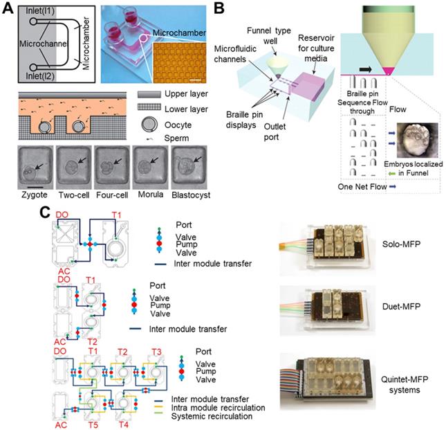
Microfluidic technology creates a dynamic environment through the flow of culture media to simulate the fluid force and mechanical stimulation of the embryo in the oviduct environment. Miyoshi et al. [219] were the first to study the effect of pulsating mechanical vibration (PMV) on porcine oocyte maturation. The cumulus-oocyte complex was treated with a 20 Hz pulsating mechanical vibration (PMV). The results show that PMV-treated oocytes have a higher blastocyst rate. Regarding the vibration frequency, the frequency of cilia beating increases significantly after ovulation in the human isthmus and ampulla [165.220]. Second, the frequency of cilia beating is different, roughly distributed at approximately 5-20 Hz [221]. Y.S. Heo et al. [222] designed a microfluidic culture system that uses microchannels as a channel for fluid to flow through the microfunnel where the embryo is located. The designed culture microfunnel minimizes the mechanical force generated by the fluid flowing through the channel. The microfunnel here positions multiple embryos together, provides a liquid storage container, buffers the biochemical exchange rate of liquid and fluid, and reduces the mechanical stimulation of the channel fluid to the embryo. The system uses a pin actuator to replace the traditional peristaltic pump to produce pulsation and peristalsis. The microchannel can generate liquid pulses with a periodic frequency of 0.135 Hz. Through simulation, the average shear force per unit area of the microchannel is 1.99×10⁻³ dyn/cm2, and the average shear force per unit area of the microfunnel is 3.55×10⁻³ dyn/cm2. Compared with static culture, dynamic funnel culture significantly improved the blastocyst rate and pregnancy rate, as shown in Figure 14B.
The method of culturing mammalian cells in vitro simulates the physical and chemical microenvironment. The typical medium composition is based on basic nutrients and some specialized factors, which are randomly mixed in a static culture environment. Cytokines and endocrine signals at the cell-cell and tissue levels are not integrated into the signalling pathway. Xiao et al. [223] designed a microfluidic platform (EVATAR) that integrates reproductive tract tissues and peripheral organs. This device can simulate the endocrine circulation of the female reproductive tract, ovaries, fallopian tubes, uterus, and cervix and realize the circulation of all organizations, as shown in Figure 14C. Gametes and early embryos are in close contact with epithelial cells when they are transported in the oviduct. Previous research on the in vitro culture of epithelial cells mainly focused on the monolayer culture of epithelial cells and the culture of fallopian tube tissue explants. Explant culture mainly uses epithelial cells to form ciliated beating vesicles. In monolayer culture, epithelial cells rapidly polarize and differentiate, becoming flat cells that lose their cilia and secretory ability.
At present, there are some microfluidic devices combined with pseudo-tubal dynamic culture and co-culture systems. Paula et al. [224] used early pig embryos as the research object. When the culture distance between embryos ranged from 81 μm to 160 μm, the fertilized ovum satisfactorily developed to the blastocyst stage. As the distance increased, the blastocyst development rate decreased significantly, verifying that the diffuse paracrine/autocrine factors produced by early pig embryos can promote in vitro culture between embryos. Michelle et al. [197] proved that preimplantation mouse embryos can produce factors that stimulate culture, and the embryos will stimulate each other. When more embryos are implanted in the same droplet, the more embryos will reach the blastocyst stage. When low-quality and high-quality embryos are cultured in the same droplet, the two will interact. High-quality embryos will have a positive effect on low-quality embryos. In contrast, low-quality embryos will have an adverse effect on high-quality embryos. U. Sanmee et al. [225] found that by co-culturing different proportions of semi-destructive and intact 4-cell embryos, the blastocyst rate of the former was increased, while the latter exhibited no significant change, verifying that high-quality embryos have a beneficial effect on low-quality embryos. Co-cultivation between embryos is also a way to improve the quality of embryos in vitro. Xie Lan et al. [226] designed a new type of microfluidic device in which each step of in vitro fertilization is integrated into the device, including ovum positioning, sperm screening, fertilization and other steps. An array of 4×4 cells is designed. Each cell is a circular fence structure composed of 8 pillars. The inner diameter of the cell is 400 microns to capture 1 to 4 oocytes, and the gap between the pillars is 50 microns to facilitate the passage of sperm, as shown in Figure 15A. Connecting the 4 linear channels with the oocyte positioning area can effectively screen sperm, quickly replace the culture medium, remove unattached and dead sperm, and provide a gentle and rapid medium replacement method. The damage to the embryo caused by the embryo from one droplet to another is avoided. Through dynamic monitoring of embryo development, the microfluidic chip can successfully perform in vitro fertilization, and the growth rate of embryos is similar to that of conventional in vitro fertilization (p>0.1).
Uterine-like co-culture microfluidic chip (A) A novel microdevice that integrates each step of IVF, including oocyte positioning, sperm screening, fertilization, medium replacement, and embryo culture. (B) A U-shaped porous membrane three-dimensional fallopian tube model chip. (C) An oviduct-on-a-chip platform to better investigate the mechanisms related to (epi)genetic reprogramming and the degree to which they differ between in vitro and in vivo embryos. (D) A microfluidic chip co-cultured with embryos and endometrial stromal cells. Adapted with permission from [226], copyright 2011 American Chemical Society, and [227], copyright 2017 Royal Society of Chemistry, and [228], copyright 2018 Nature Pub. Group, and [229], copyright 2016 Elsevier Sequoia.
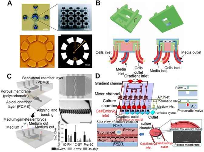
Ferraz et al. [227] designed a U-shaped porous membrane three-dimensional fallopian tube model chip, including a basolateral perfusion chamber that simulates blood circulation and an independent apical perfusion chamber that simulates fluid movement in the fallopian tube lumen. The system can simulate endocrine changes in the body and promote an increase in beneficial substances and the removal of harmful substances. The use of porous membranes ensures that epithelial cells are cultured at the air-liquid interface, maintaining cilia beating and epithelial secretion. This device can effectively avoid multiple sperm fertilization and parthenogenesis, as shown in Figure 15B. Furthermore, Ferraz et al. [228] found that fallopian tube model chips made of conventional materials produce toxic substances (phthalates and ethylene glycol) during cell culture, which affect early embryonic development. PDMS has good biocompatibility. Ferrza used PDMS materials to further optimize and design a microfluidic fallopian tube chip platform, which contains two independent and perfusable compartments, which are separated by a porous membrane. The apical chamber continuously perfuses the fallopian tube epithelial cell layer with IVF and IVP devices, and the chamber is also designed with a column for capturing oocytes and embryos. The basal compartment is used to simulate the changes in circulating hormones that occur during ovulation. This simulated fallopian tube platform introduces changes in the culture conditions and the oestrus cycle at the same time, which can better simulate the environment in the body. By using the immunofluorescence labelling method to detect changes in the global DNA methylation status, the embryonic development ability can be revealed after the activation of the embryonic genome. The first genetic comparison of the 4.8.16-cell and embryonic stages of bovine embryo development found that compared with standard IVP conditions, the platform can improve the delay of zygotic transcriptome activation, as shown in Figure 15C. Chang et al. [229] designed a microfluidic chip in which embryos and endometrial stromal cells were co-cultured, as shown in Figure 15D. A semicircular arc-shaped microstructure was designed on the side wall of the culture chamber. The embryo uses the microstructure to generate mechanical stimulation to the embryo under the drive of fluid, which simulates the cilia of the embryo in the fallopian tube. In addition, the chip simulates hormone changes during the menstrual cycle and creates a gradient channel that automatically generates different concentrations of steroid hormones. In addition, multiple culture chambers are connected to each other through microchannels to produce a group culture effect, which is conducive to the exchange of autocrine and paracrine factors between embryos. In the culture room, endometrial stromal cells are cultured on the porous membrane, and fresh culture fluid is delivered to the cells on the top and bottom, effectively avoiding the adverse effects on the embryo caused by apoptosis. Experimental results showed that the blastocyst development rate of 67±10.05% under the co-culture condition was higher than that of 49±8.19% under the non-co-culture condition. The co-culture condition was more conducive to the culture and development of the culture. In short, with the future development of microfluidic technology, the integration of co-culture technology with new culture materials and culture devices can create an in vitro culture environment closer to that of a living body for early embryos and promote the development of in vitro culture technology for early mouse embryos.
4.3.2 Droplet-type microfluidic dynamic culture system
When in vitro, laminar flow microfluidic devices mainly provide a microchannel, microstructure and continuous flow culture liquid, while fluid mechanics technology is used to manipulate cells and simulate the physiological microenvironment experienced in vivo [230]. However, laminar flow microfluidic devices also have disadvantages. For example, the culture method may cause pollution problems, and it is difficult to manipulate and observe a single cell or several cells in a continuous flow channel. DMF (digital microfluidic) platform has become a good alternative. The DMF platform can bypass channels, pumps and valves to control fluid movement and avoid the problem of blockage caused by this effect [231]. In its most popular way, DMFs can use electric fields (including EWOD and DEP) on the electrode array to process microscale discrete droplets [232]. The DMF platform has become a very good tool for manipulating trace reagents and target cells in a single droplet and has been widely used in the field of cell manipulation (e.g., cell culture [233-236], cell sorting and concentration [237-240], and single-cell manipulation and analysis [241-244]) in recent years. The DMF platform has the advantages of low reagent usage, a simple structure, and a high degree of automation [245]. Irena et al. designed the first chip platform for complete mammalian culture driven by DMFs, integrating all the steps (seeding, growing, separating and reseeding) of mammalian cell culture into the DMF platform to realize the automated cultivation of mammalian cells [233].
The EWOD (electrowetting on dielectric) system is a droplet driving mechanism in the DMF platform and is one of the most advanced methods for manipulating droplets. The EWOD system is derived from the electrowetting phenomenon that changes the contact angle of the liquid. By applying an AC voltage to the electrode directly below the surface of the substrate, the wettability of the droplet surface is changed locally, and the attraction that drives the movement of the droplet is generated. It is usually quantified by the degree of contact angle reduction. The change in the contact angle in the EWOD system is generally defined by the Young-Lippmann equation [246], and the contact angle is usually related to factors such as the operating frequency, dielectric constant, and droplet conductivity. This system can easily create, transfer, separate and combine micron- and nanometre-sized droplets, and its operation is stable and repeatable [245]. Son et al. [247] used double-plate digital microfluidic device technology to transfer live yeast droplets and zebrafish embryo droplets and mixed the two droplets after transmission to achieve dechlorination. The transferred zebrafish embryos developed normally and hatched. This finding proves that the DMF platform can manipulate cells as well as larger embryos to maintain their viability, as shown in Figure 16A. The DMF platform can transport oocytes or embryos to a designated location for in vitro fertilization of oocytes or the chemical and mechanical treatment of embryos. Derek G. Pyne et al. [248] used digital microfluidic equipment to automate the processing of vitrified embryos, as shown in Figure 16B, including droplet delivery, mixing, distribution and splitting. Mouse embryos were placed in droplets that function as capillaries, and a single mouse embryo was transported through the DMF platform during the complete vitrification process. The embryo survival rate and development rate obtained by this device are equivalent to those obtained manually. This method has the advantages of automatic operation, the generation of a cryoprotectant concentration gradient and the feasibility of loading and retrieving embryos. Huang et al. [249] described a new type of digital microfluidic device with the EWOD system, as shown in Figure 16C, to cultivate mammalian embryos in a single droplet. Using the EWOD system to provide a dynamic fluid environment, this device provides a discontinuous microfluidic environment to simulate the in vivo embryonic development environment, promoting mouse embryo cleavage and the development to the preimplantation stage. However, this system cannot provide stable embryo movement speed; that is, the embryo movement speed in the droplet is random. Huang further designed a new type of circular DMF chip [250], as shown in Figure 16D, with the functions of in vitro fertilization and in vitro culture. In the experiment, HTF droplets containing male and female mouse gametes were mixed with DMF-treated droplets to form fertilized ova. The fertilized embryos were dynamically cultured and transported between electrode pairs at a certain interval. The in vitro fertilization rate of the DMF platform was 8.7% higher than that of traditional petri dishes, and the number of embryos that have developed to 8-cells was similar. The ring-shaped DMF chip solves the problem of gas exchange during embryo culture. Embryos in dynamic culture develop faster than those in static culture.
DMF-style dynamic cultivation system. (A) Dual-plate digital microfluidic device EWOD technology. (B) Digital microfluidic equipment to automate the processing of vitrified frozen embryos. (C) A microfluidic microchannel system for IVF is considered to provide an improved in vivo-mimicking environment to enhance the development of an embryo culture system before implantation. (D) A new DMF chip design with a PDMS ring has solved the problem of gas exchange during long-term embryo culture. Adapted with permission from [247], copyright 2009 Royal Society of Chemistry, and [248], copyright 2014 Public Library of Science, and [249], copyright 2015 Public Library of Science, and [250], copyright 2015 IEEE.
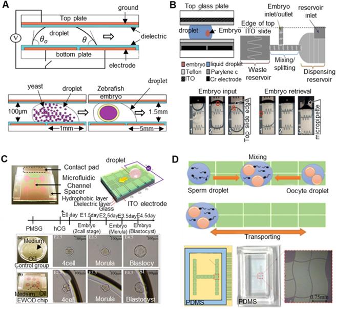
4.4 Conclusion for early embryo in vitro culture
In related research regarding the in vitro culture of early embryos, researchers have been constantly exploring the reproductive mechanism of early embryo development and have found that there are many complex factors affecting early embryo development. On the one hand, based on cost, operability and other factors, the conventional in vitro culture method of static culture still occupies a dominant position in many biological and medical laboratories. To improve this technology, some studies have introduced new culture materials to improve the culture effect and tap its potential. On the other hand, the reproductive mechanism of early embryos shows that dynamic culture technology is the most natural form of a culture system and will be the future development direction of in vitro culture technology. A large number of studies have focused on the tubal/uterine dynamic culture system. With the development of microfluidic technology, dynamic culture technology has been greatly promoted. By simulating organ-like structural microenvironments and dynamic biochemical/mechanical stimulation processes, various complex culture systems have been constructed to approach the natural development environment of early embryos, which has indeed brought about a substantial increase in the embryo development rate and has shown great advantages. There is no problem in the theoretical verification. However, considerable effort is required to replace traditional in vitro culture technology with practical systems. The system is too complex, the processing cost is high, and the reusability and ease of use are not strong. Cost reduction and moving these advanced technologies from the laboratory to industry are key problems to be solved in the future.
5. Conclusion and prospect
From the perspective of engineering, this article presents the three high-risk nodes that most affect the success rate of the entire process of embryo engineering technology according to its current status and development trend, namely, oocyte micromanipulation, oocyte electrical activation/reconstructed embryo electrofusion and in vitro culture of early embryos. Researchers have started from these three critical nodes and developed numerous novel machine-assisted technologies to improve the effect. The main research content is shown in Figure 17. However, machine-assisted technology has never shown much advantage in terms of the core index, i.e., the success rate. This reason requires us to have a more in-depth understanding about the technical process of embryo manipulation. The embryo engineering technology process is first a life development process, with its own laws of life activities, and the operation technology without an in-depth analysis of its internal physiological mechanism cannot guarantee to maximize its advantages. Second, embryo operation technology is a sequential operation process, and its influencing factors are very complicated. All the factors of the previous operation node will have an impact on the following steps, and the improvement effect of some factors on a single node will be diluted by other nodes. In future related research, we should no longer pursue the ultimate improvement of certain aspects of technology in one aspect. Instead, we should have a systematic concept. First, we should find the weak bottleneck in the most critical nodes that affects the success rate to make breakthroughs, then take the process as a whole, conduct systematic analyses and repeated corrections, and finally achieve a substantial increase in the overall success rate of machine-assisted embryo engineering technology. The details are as follows:
Critical nodes in embryo engineering technology and their main research contents.
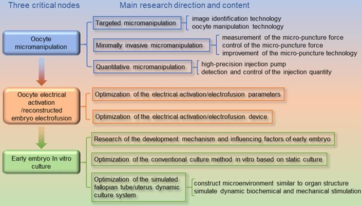
In related research on oocyte micromanipulation, although researchers have invested substantial energy, they have tried to use the high sensitivity, high positioning accuracy, and high stability of machines to compensate for deficiencies in the stability of manual operation to achieve an improved success rate. However, the effect of machine-assisted micromanipulation is inadequate, and the reasons may be as follows. First, the existing micromanipulation technology lacks scientific theoretical guidance. The selection of existing micromanipulation strategies (injection path, angle, etc.) is basically based on manual operation experience. Second, researchers generally regard the target oocyte as a cortical membrane model. Research on oocyte damage has basically focused on the zona pellucida, but the internal structures of oocytes are often ignored. However, these internal microstructures, such as the nucleus and skeleton, are more important to oocytes. In future research, a guiding strategy for robotic oocyte micromanipulation should be established to provide theoretical guidance for micromanipulation instead of continuing to use the empirical conclusions of manual manipulation. The evaluation mechanism of the degree of damage in oocyte micromanipulation should be established and fed back to the experiment to help find the best operation mode and parameters.
In research on oocyte electrical activation/reconstructed embryo electrofusion, we should first consider the characteristics of oocyte electrical stimulation, combine microfluidic technology and micromanipulation technology, and develop a new precise electrical stimulation device suitable for oocyte electrical activation/reconstructed embryo electrofusion. Second, we should deeply reveal the physiological mechanism of oocyte electrical activation/reconstructed embryo electrofusion, study the effect of the different parameters of electrical stimulation signals on oocytes, and realize the optimization of electrical stimulation parameters. Through the combination of these two aspects, the best electrical stimulation effect can be obtained by trial and error correction.
In the study of the in vitro culture of early embryos, although researchers have constructed a variety of organ-like structural microenvironments and complex culture systems of dynamic biochemical/mechanical stimulation processes, they have brought a substantial increase in the rate of embryo development. However, there is still a long way to go for all kinds of systems to replace traditional in vitro culture technology. The existing systems are too complex, the processing cost is high, and the reusability and ease of use are not strong. To make it out of the laboratory, future work should focus on system improvement through the introduction of new processing technology, new materials and new structures, reduce the cost of products, strengthen modular design, increase the reuse rate of products and reduce the cost of consumables. Only in this way can actual operators use and promote the development of related industries.
In addition, although a large number of new technologies have been developed to improve the various nodes of embryo manipulation technology, how can we evaluate its effect? As the influencing factors of embryo engineering technology are too complicated, it is still very difficult to evaluate them. At present, research related to embryo engineering technology basically regards the embryo development rate/survival rate after surgery as the evaluation standard of the pros and cons of the new technology. In reproductive medicine, the final effect of the entire operation process can only be evaluated in the last in vitro culture link based on experience or image data, combined with the static morphological quality assessment system and the jet lag embryo culture detection system. Generally, this kind of evaluation system is very rough, empirical and subjective and is too strong to meet the developmental needs of embryo manipulation technology. Quantitative monitoring methods should be introduced for the entire process of embryo engineering technology, combined with complex models for predictive analysis, so that problems can be identified. Only by performing targeted improvements can machine-assisted embryo manipulation technology achieve a substantial increase in the overall success rate, show its superiority over manual operations, and promote technological upgrading. Ultimately, as a basic technology, this technology gives a considerable boost to related biomedical research and industry.
Acknowledgements
This research was funded by the National Key R&D Program of China (2018YFB1304905), the Natural Science Foundation of Jiangsu Province of China (BK20171215), the Natural Science Foundation of the Jiangsu Higher Education Institutions of China (17KJA460008), and the Suzhou Science and Technology Innovation Policy Funded Project (SCJ 2020 No.45).
Author contributions
Y.M. and M.G. wrote the first draft. H.H and Y.Z. provided writing guidance and manuscript revision.
Supplementary Material
Supplementary figures and tables.
Competing Interests
The authors have declared that no competing interest exists.
References
1. Roy S, Gandra D, Seger C, Biswas A, Kushnir VA, Gleicher N. et al. Oocyte-derived factors (GDF9 and BMP15) and FSH regulate AMH expressionvia modulation of H3K27AC in granulosa cells. Endocrinology. 2018;159:3433-45
2. Wilmut I, Schnieke AE, McWhir J, Kind AJ, Campbell KHS. Viable offspring derived from fetal and adult mammalian cells. Nature. 1997;385:810-3
3. Fatira E, Havelka M, Labbé C, Depincé A, Pšenička M, Saito T. A newly developed cloning technique in sturgeons; an important step towards recovering endangered species. Sci Rep. 2019;9:10453
4. Marianne E D. Infertility, assisted reproduction technologies and imprinting disturbances: a Dutch study. Hum Reprod. 2007 9
5. Bavister BD. How animal embryo research led to the first documented human IVF. Reprod Biomed Online. 2002;4:24-9
6. Esteves SC, Roque M, Bedoschi G, Haahr T, Humaidan P. Intracytoplasmic sperm injection for male infertility and consequences for offspring. Nat Rev Urol. 2018;15:535-62
7. Sirpa S. The interface between assisted reproductive technologies and genetics: technical, social, ethical and legal issues. Eur J Hum Genet. 2006 5
8. Kim MJ, Oh HJ, Kim GA, Setyawan EMN, Choi YB, Lee SH. et al. Birth of clones of the world's first cloned dog. Sci Rep. 2017;7:15235
9. King TJ. Chapter 1 Nuclear Transplantation in Amphibia. In: Prescott DM, editor. Methods Cell Biol Academic Press. 1966 p: 1-36
10. Solter D. Mammalian cloning: advances and limitations. Nat Rev Genet. 2000;1:199-207
11. Liu Z, Cai Y, Wang Y, Nie Y, Zhang C, Xu Y. et al. Cloning of macaque monkeys by somatic cell nuclear transfer. Cell. 2018;174:245
12. Selokar NL, Sharma P, Saini M, Sheoran S, Rajendran R, Kumar D. et al. Successful cloning of a superior buffalo bull. Sci Rep. 2019;9:11366
13. Seol JG, Kim SH, Jin D-I, Hong SP, Yoo JY, Choi KM. et al. Production of transgenic cloned miniature pigs with membrane-bound human fas ligand (FasL) by somatic cell nuclear transfer. Nat Precedings. 2010
14. Zhang W, Wang J, Li P, Wu C, Zhang H, Zhang W. et al. Transferrin-navigation Nano Artificial Antibody Fluorescence Recognition of Circulating Tumor Cells. Sci Rep. 2017;7:10142
15. Zhang Y, Tan KK, Huang S. Vision-Servo System for Automated Cell Injection. IEEE Trans Ind Electron. 2009;56:231-8
16. Mattos L, Grant E, Thresher R, Kluckman K. New developments towards automated blastocyst microinjections. Proc IEEE Int Conf Robot Autom. 2007 p: 1924-9
17. Sun X, Zhu X, Wang P, Chen H. A rview of robot control with visual servoing. IEEE Annu Int Conf Cyber Tech Autom Control Intell Syst. 2018 p: 116-21
18. Ni Z, Bolopion A, Agnus J, Benosman R, Regnier S. Asynchronous event-based visual shape tracking for stable haptic feedback in microrobotics. IEEE Trans Robot. 2012;28:1081-9
19. Anis YH, Mills JK, Cleghorn WL. Vision-based measurement of microassembly forces. J Micromech Microeng. 2006;16:1639-52
20. Tamadazte B, Piat NL, Dembélé S. Robotic micromanipulation and microassembly using monoview and multiscale visual servoing. IEEE ASME Trans Mechatron. 2011;16:277-87
21. Sun Y, Nelson BJ. Biological cell injection using an autonomous microrobotic system. Int J Rob Res. 2002;21:861-8
22. Liu J, Gong Z, Tang K, Lu Z, Ru C, Luo J. et al. Locating end-effector tips in robotic micromanipulation. IEEE Trans Robot. 2014;30:125-30
23. Kuba H, Hotta K, Takahashi H. Automatic particle detection and counting by one-class SVM from microscope image. Int Conf Adv Neuro-Inf Process. 2009 p: 361-8
24. Jun L. Quantitative analysis of locomotive behavior of human sperm head and tail. IEEE Trans Biomed Eng. 2013 2
25. Spontón H, Cardelino J. A review of classic edge detectors. Image Process on Line. 2015;5:90-123
26. Heath M, Sarkar S, Sanocki T, Bowyer K. Comparison of edge detectors: a methodology and initial study. Comput Vis Image Underst. 1998;69:38-54
27. Han J, Yang C, Zhou X, Gui W. A new multi-threshold image segmentation approach using state transition algorithm. Appl Math Model. 2017;44:588-601
28. Wenshuo G, Xiaoguang Z, Lei Y, Huizhong L. An improved sobel edge detection. Int Conf Compu Sc Inf Technol. 2010 p: 67-71
29. Shrivakshan GT, Chandrasekar C. A comparison of various edge detection techniques used in image processing. Int J Com Sci Issues. 2012
30. Yuan L, Xu X. Adaptive image edge detection algorithm based on canny operator. Int Conf Adv Inf Technol Sens Appl. 2015 p: 28-31
31. Zhang L, Ye Y, Dhar R, Deng J, Tang H. Estimating dynamic cellular morphological properties via the combination of the RTCA system and a hough-transform-based algorithm. Cells. 2019 8
32. Mukhopadhyay P, Chaudhuri BB. A survey of hough transform. Pattern Recognit. 2015;48:993-1010
33. Zhu S, Gao R. A novel generalized gradient vector flow snake model using minimal surface and component-normalized method for medical image segmentation. Biomed Signal Process Control. 2016;26:1-10
34. Huang H, Sun D, Mills J, Cheng SH. Robotic cell injection system with position and force control: toward automatic batch biomanipulation. IEEE Trans Robot. 2009;25:727-37
35. Leung C, Lu Z, Zhang XP, Sun Y. Three-dimensional rotation of mouse embryos. IEEE Trans Biomed Eng. 2012;59:1049-56
36. Chen D, Sun M, Zhao X. A cell polar body positioning method based on SVM classification. IEEE ROBIO. 2014 p: 505-9
37. Chen D, Sun M, Zhao X. Oocytes polar body detection for automatic enucleation. Micromachines (Basel). 2016 7
38. Wang Y, Liu Y, Sun M, Zhao X. Deep-learning-based polar-body detection for automatic cell manipulation. Micromachines (Basel). 2019 10
39. Wang Z, Feng C, Ang WT, Tan SYM, Latt WT. Autofocusing and polar body detection in automated cell manipulation. IEEE Trans Biomed Eng. 2017;64:1099-105
40. Saadat M, Hajiyavand AM, Singh Bedi AP. Oocyte positional recognition for automatic manipulation in ICSI. Micromachines (Basel). 2018 9
41. Deng Y, Ye X, Cao B, Zhou J, Liufu T, Wang X. et al. Application of fluorescence microscopy in research of oocyte meiosis. Chin J Lasers. 2018 45
42. T D. Dynamic imaging of the metaphase II spindle and maternal chromosomes in bovine oocytes: implications for enucleation efficiency verification, avoidance of parthenogenesis, and successful embryogenesis. Biol Reprod. 2000 1
43. Gilchrist R, Nayudu P, Nowshari M, Hodges K. Meiotic competence of marmoset monkey oocytes is related to follicle size and oocyte-somatic cell associations. Biol Reprod. 1995;52:1234-43
44. Sereni E, Sciajno R, Fava L, Coticchio G, Bonu MA, Borini A. A polscope evaluation of meiotic spindle dynamics in frozen-thawed oocytes. Reprod Biomed Online. 2009;19:191-7
45. Nandedkar P, Chohan P, Patwardhan A, Gaikwad S, Bhartiya D. Parthenogenesis and somatic cell nuclear transfer in sheep oocytes using polscope. Indian J Exp Biol. 2009;47:550-8
46. Wang W-H, Keefe D. Spindle observation in living mammalian oocytes with the polarization microscope and its practical use. Cloning Stem Cells. 2002;4:269-76
47. Madaschi C, Aoki T, Braga D, Figueira R, Francisco L, Iaconelli A. et al. Zona pellucida birefringence score and meiotic spindle visualization in relation to embryo development and ICSI outcomes. Reprod Biomed Online. 2009;18:681-6
48. Wang Z, Chen G, Huang H, Gao P, Wang Z, Sun D. et al. A novel shape information based spindle positioning method with the polarized light microscopy. IEEE Int Conf Nano. 2013 p: 150-3
49. Chen G, Gao P, Huang H, Wang Z, Tao C, Chen L. et al. A novel multi-cue based image fusion method combining multi-principle microscopy images towards Nuclear transfer technology. IEEE Int Conf Nano Mol Med Eng. 2013 p: 11-5
50. Lu Z, Moraes C, Zhao Y, You L, Simmons CA, Sun Y. A micromanipulation system for single cell deposition. IEEE Int Conf Robot Autom. 2010 p: 494-9
51. Liu Y, Maosheng C, Huang J, Sun M, Zhao X, Zhao Q. Robotic microcapillary aspiration for multiple cells. Micromachines (Basel). 2019;10:348
52. Lu Z, Chen PCY, Nam J, Ge R, Lin W. A micromanipulation system with dynamic force-feedback for automatic batch microinjection. J Micromech Microeng. 2007;17:314-21
53. Liu X, Sun Y. Microfabricated glass devices for rapid single cell immobilization in mouse zygote microinjection. Biomed Microdevices. 2009;11:1169
54. Ghaemi R, Arefi P, Stosic A, Acker M, Raza Q, Roger Jacobs J. et al. A microfluidic microinjector for toxicological and developmental studies in Drosophila embryos. Lab chip. 2017;17:3898-908
55. Andersson H, van den Berg A. Microfluidic devices for cellomics: a review. Sens Actuators B Chem. 2003;92:315-25
56. Wang Z, Feng C, Muruganandam R, Ang WT, Tan SYM, Latt WT. Three-dimensional cell rotation with fluidic flow-controlled cell manipulating device. IEEE ASME Trans Mechatron. 2016;21:1995-2003
57. Hwang H, Lu H. Microfluidic tools for developmental studies of small model organisms-nematodes, fruit flies, and zebrafish. Biotechnol J. 2013;8:192-205
58. Shin YK, Kim Y, Kim J. Automated microfluidic system for orientation control of mouse embryos. IEEE RSJ Int Conf Intell Robot Syst. 2013 p: 496-501
59. Park K, Kabiri S, Sonkusale S. Dielectrophoretic lab-on-CMOS platform for trapping and manipulation of cells. Biomed Microdevices. 2016;18:6
60. Hunt TP, Westervelt RM. Dielectrophoresis tweezers for single cell manipulation. Biomed Microdevices. 2006;8:227-30
61. Jen C-P, Chen T-W. Trapping of cells by insulator-based dielectrophoresis using open-top microstructures. Microsyst Technol. 2008;15:1141
62. Huang L, Zhao P, Wang W. 3D cell electrorotation and imaging for measuring multiple cellular biophysical properties. Lab chip. 2018;18:2359-68
63. Chow YT, Man T, Acosta-Vélez GF, Zhu X, Wen X, Chung P-S. et al. Liquid metal-based multifunctional microcapillary for 4D single cell manipulation. Adv Sci (Weinh). 2018;5:1700711
64. Huang K, Abu Ajamieh I, Cui Z, Lai J, Mills J, Chu H. Automated embryo manipulation and rotation via robotic nDEP-tweezers. IEEE Trans Biomed Eng. 2020 PP: 1
65. Wu MC, Jamshidi A, Neale SL, Tien M, Ohta AT, Yu K. Optoelectronic tweezers - a new parallel optical manipulation tool. Int Solid State Sens Actuators Microsyst Conf. 2009 p: 1582-5
66. Grier DG. A revolution in optical manipulation. Nature. 2003;424:810-6
67. McAlinden N, Glass DG, Millington OR, Wright AJ. Accurate position tracking of optically trapped live cells. Biomed Opt Express. 2014;5:1026-37
68. Ruixue Z, Haiyan W, Debin Z, Xiaowen HU, Xiaobo X. New advances in the application of optical tweezers in biology. Ji Guang Sheng Wu Xue Bao. 2017
69. Eguchi Y, Ogiue-Ikeda M, Ueno S. Control of orientation of rat schwann cells using an 8-T static magnetic field. Neurosci Lett. 2003;351:130-2
70. Tierno P, Golestanian R, Pagonabarraga I, Sagués F. Controlled swimming in confined fluids of magnetically actuated colloidal rotors. Phys Rev Lett. 2008;101:218304
71. Ogiue-Ikeda M, Ueno S. Magnetic cell orientation depending on cell type and cell density. IEEE Trans Magn. 2004;40:3024-6
72. Pivetal J, Royet D, Ciuta G, Frenea-Robin M, Haddour N, Dempsey NM. et al. Micro-magnet arrays for specific single bacterial cell positioning. J Magn Magn Mater. 2015;380:72-7
73. Chen X, Hoop M, Mushtaq F, Siringil E, Hu C, Nelson B. et al. Recent developments in magnetically driven micro- and nanorobots. Appl Mater Today. 2017;9:37-48
74. Wei Y, Xu Q. A survey of force-assisted robotic cell microinjection technologies. IEEE Trans Autom Sci Eng. 2019;16:931-45
75. Yang C, Xie Y, Liu S, Sun D. Force modeling, identification, and feedback control of robot-assisted needle insertion: a survey of the literature. Sensors (Basel). 2018;18:561
76. Jumpertz R, Hart Avd, Ohlsson O, Saurenbach F, Schelten J. Piezoresistive sensors on AFM cantilevers with atomic resolution. Microelectron Eng. 1998;41-42:441-4
77. Beutel T, Ferreira N, Balck A, Leester-Schadel M, Buttgenbach S. Cell manipulation system based on a self-calibrating silicon micro force sensor providing capillary status monitoring. IEEE Sens J. 2012;12:3075-81
78. Sun Y, Nelson BJ, Potasek DP, Enikov E. A bulk microfabricated multi-axis capacitive cellular force sensor using transverse comb drives. J Micromech Microeng. 2002;12:832-40
79. Sun Y, Nelson BJ. MEMS capacitive force sensors for cellular and flight biomechanics. Biomed Mater. 2007;2:S16-S22
80. Muntwyler S, Beyeler F, Nelson BJ. Three-axis micro-force sensor with sub-micro-newton measurement uncertainty and tunable force range. J Micromech Microeng. 2009;20:025011
81. Beyeler F, Muntwyler S, Nelson BJ. A six-axis MEMS force-torque sensor with micro-newton and nano-newtonmeter resolution. J Microelectromech Syst. 2009;18:433-41
82. Wei Y, Xu Q. Design of a PVDF-MFC force sensor for robot-sssisted single cell microinjection. IEEE Sens J. 2017;17:3975-82
83. Huang H, Sun D, Su H, Mills JK. Force sensing and control in robot-assisted suspended cell injection system. Adv Robot Virtual Real. 2012 p: 61-88
84. Xie Y, Sun D, Liu C, Tse H, Cheng SH. A force control approach to a robot-assisted cell microinjection system. Int J Rob Res. 2010;29:1222-32
85. Zhang XJ, Zappe S, Bernstein RW, Sahin O, Chen C, Fish M. et al. Integrated optical diffractive micrograting-based injection force sensor. Int Solid State Sens Actuators Microsyst Conf. 2003 p: 1051-4
86. Su H, Fischer GS. A 3-axis optical force/torque sensor for prostate needle placement in Magnetic resonance imaging environments. IEEE Int Conf Technol Pract Robot Appl. 2009 p: 5-9
87. Xiaojing Z, Scott MP, Quate CF, Solgaard O. Microoptical characterization of piezoelectric vibratory microinjections in drosophila embryos for genome-wide RNAi screen. J Microelectromech Syst. 2006;15:277-86
88. Greminger M, Nelson B. Vision-based force measurement. IEEE Trans Pattern Anal Mach Intell. 2004;26:290-8
89. Liu X, Wang W, Lansdorp BM, Sun Y. Vision-based cellular force measurement using an elastic microfabricated device. IEEE RSJ Int Conf Intell Robot Syst. 2006 p: 1378-83
90. Karimirad F, Chauhan S, Shirinzadeh B. Vision-based force measurement using neural networks for biological cell microinjection. J Biomech. 2014;47:1157-63
91. Washio T, Chinzei K. Needle force sensor, robust and sensitive detection of the instant of needle puncture. Med Image Comput Comput Assist Interv. 2004 pp:113-120
92. Fukushima Y, Saito K, Naemura K. Estimation of the cutting force using the dynamic friction coefficient obtained by reaction force during the needle insertion. Procedia CIRP. 2013;5:265-9
93. Lorenzo DD, Koseki Y, Momi ED, Chinzei K, Okamura AM. Coaxial needle insertion assistant with enhanced force feedback. IEEE Trans Biomed Eng. 2013;60:379-89
94. Katsura S, Matsumoto Y, Ohnishi K. Modeling of force sensing and validation of disturbance observer for force control. IEEE Trans Ind Electron. 2007;54:530-8
95. Karimirad F, Shirinzadeh B, Zhong Y, Smith J, Mozafari MR. Modelling a precision loadcell using neural networks for vision-based force measurement in cell micromanipulation. IEEE ASME Int Conf on Adv Intell Mechatron. 2013 p: 106-10
96. Sun Z, Hao L, Chen W, Li Z. Robotic cell injection force control based on static PVDF sensor and Fuzzy-PID control method. Int J Appl Electrom. 2013;41:73-86
97. Wang G, Xu Q. Design and precision position/force control of a piezo-driven microinjection system. IEEE ASME Trans Mechatron. 2017;22:1744-54
98. Laffafian I, Hallett M. Lipid-assisted microinjection: introducing material into the cytosol and membranes of small cells. Biophys J. 1998;75:2558-63
99. Kim D-H, Sun Y, Yun S, Kim B, Hwang C, Nelson B. et al. Mechanical property characterization of the zebrafish embryo chorion. Conf Proc IEEE Eng Med Biol Soc. 2004;7:5061-4
100. Ron-El R, Liu J, Nagy Z, Joris H, van den abbeel E, Van Steirteghem A. Intracytoplasmic sperm injection in the mouse. Hum Reprod. 1995;10:2831-4
101. Ediz K, Olgac N. Effect of mercury column on the microdynamics of the piezo-driven pipettes. J Biomech Eng. 2005;127:531-5
102. Gan Y, Chen Z. A study of the zona piercing process in piezodriven intracytoplasmic sperm injection. J Appl Phys. 2008;104:044702
103. Ergenc AF, Li MW, Toner M, Biggers JD, Lloyd KC, Olgac N. Rotationally oscillating drill (Ros-Drill) for mouse ICSI without using mercury. Mol Reprod Dev. 2008;75:1744-51
104. Huang H, Mills JK, Lu C, Sun D. A universal piezo-driven ultrasonic cell microinjection system. Biomed Microdevices. 2011;13:743-52
105. Huang H, Mills JK, Sun D. A new piezo-driven ultrasonic cell microinjection system. IEEE Int Conf Inform Autom. 2010 p: 18-23
106. Johnson W, Dai C, Liu J, Wang X, Luu DK, Zhang Z. et al. A flexure-guided piezo drill for penetrating the zona pellucida of mammalian oocytes. IEEE Trans Biomed Eng. 2018;65:678-86
107. Dai C, Xin L, Zhang Z, Shan G, Wang T, Zhang K. et al. Design and control of a piezo drill for robotic piezo-driven cell penetration. IEEE Robot Autom Lett. 2020;5:339-45
108. Fei Liu, Dan Wu, Xiaoyong Ken. et al. Analyses of the cell mechanical damage during microinjection. Soft matter. 2015 pp: 1434-42
109. Wang WH, Liu XY, Sun Y. High-throughput automated injection of individual biological cells. IEEE Trans Autom Sci Eng. 2009;6:209-19
110. Kwon H, Park H-s, Yu J, Hong S, Choi Y. Spatio-temporally controlled transfection by quantitative injection into a single cell. Biomaterials. 2015;67:225-31
111. Li N, Liu Y, Li S, Wang X, Qin Y, Sun M. et al. High-precision, pressure-driven pump for sub-picoliter scale quantitative injection. Mod Phys Lett B. 2017;31:1750148
112. Noori A, Selvaganapathy PR, Wilson J. Microinjection in a microfluidic format using flexible and compliant channels and electroosmotic dosage control. Lab chip. 2009;9:3202-11
113. Zhao Q, Wu M, Maosheng C, Qin Y, Yu J, Sun M. et al. A novel pneumatic microcapillary aspiration method using a balance pressure model. Rev Sci Instrum. 2013;84:123703
114. Wang X, Zhao Q, Wang L, Liu J, Pu H, Xie S. et al. Effect of cell inner pressure on deposition volume in microinjection. Langmuir. 2018;34:10287-92
115. Tianjun L, Liya H, Weiyi Z, Zhijun R. Study on the flowing characteristics of microcapillary in cell injection. China Mech Eng. 2004:75-8
116. Chow YT, Chen S, Wang R, Liu C, Kong C-w, Li RA. et al. Single cell transfection through precise microinjection with quantitatively controlled injection volumes. Sci Rep (UK). 2016;6:24127
117. Chow YT, Chen S, Sun D, Kong CW, Li RA, Cheng SH. A quantitative fluorescence intensity method to measure sub-picogram injection amount for tiny cell injection. IEEE Int Conf Nanotechnol. 2015 p: 1019-22
118. Huang J, Shi L, Zhou H, Wei X, Wei Y. Applied research on self-sensing micro-flow injection device based on piezoelectric ceramics. Key Eng Mater. 2015;645-646:746-55
119. Horner VL, Wolfner MF. Mechanical stimulation by osmotic and hydrostatic pressure activates drosophila oocytes in vitro in a calcium-dependent manner. Dev Biol. 2008;316:100-9
120. Saitou T, Ishikawa T, Obara K, Nakayama K. Characterization of whole-cell currents elicited by mechanical stimulation of Xenopus oocytes. Pflugers Arch. 2000;440:858-65
121. Wani NA. Chemical activation of in vitro matured dromedary camel (Camelus dromedarius) oocytes: Optimization of protocols. Theriogenology. 2008;69:591-602
122. Ware CB, Barnes FL, Maiki-Laurila M, First NL. Age dependence of bovine oocyte activation. Gamete Res. 1989;22:265-75
123. Kumar D, Gopalakrishna R, Singh AP, Ranjan R, Pandey SK, Sarkhel BC. Developmental potency of pre-implant parthenogenetic goat embryos: effect of activation protocols and culture media. In vitro Cell Dev Biol Anim. 2014;50:1-6
124. Nagai T. Parthenogenetic activation of cattle follicular oocytes in vitro with ethanol. Gamete Res. 1987;16:243-9
125. Yi YJ, Park CS. Parthenogenetic development of porcine oocytes treated by ethanol, cycloheximide, cytochalasin B and 6-dimethylaminopurine. Anim Reprod Sci. 2005;86:297-304
126. Levin M, Stevenson CG. Regulation of cell behavior and tissue patterning by bioelectrical signals: challenges and opportunities for biomedical engineering. Annu Rev Biomed Eng. 2012;14:295-323
127. Zhu J, Telfer E, Fletcher J, Springbett A, Dobrinsky J, Sousa P. et al. Improvement of an electrical activation protocol for porcine oocytes. Biol Reprod. 2002;66:635-41
128. Weaver JC, Powell KT. Theory of electroporation. Electroporation and Electrofusion in Cell Biology. 1989 p: 111-26
129. Weaver JC, Chizmadzhev YA. Theory of electroporation: A review. Bioelectrochem Bioenerg. 1996;41:135-60
130. Dermol-Černe J, Batista Napotnik T, Reberšek M, Miklavčič D. Short microsecond pulses achieve homogeneous electroporation of elongated biological cells irrespective of their orientation in electric field. Sci Rep. 2020;10:9149
131. Liu L, Moor RM. Factors affecting electrical activation of porcine oocyte matured in vitro. Anim Reprod Sci. 1997;48:67-80
132. Leal C, Liu L. Differential effects of kinase inhibitor and electrical stimulus on activation and histone H1 kinase activity in pig oocytes. Anim Reprod Sci. 1998;52:51-61
133. Liu S, Cui K, Li HL, Sun JM, Lu XR, Shen KY. et al. Comparison of chemical, electrical, and combined activation methods for in vitro matured porcine oocytes. In vitro Cell Dev Biol Anim. 2015;51:103-12
134. Zhang Y-C, Jin L, Zhu H-Y, Guo Q, Li X-C, Zhang G-L. et al. The developmental competence of oocytes parthenogenetically activated by an electric pulse and anisomycin treatment. Biotechnol Lett. 2017;39:189-96
135. Hosseini SM, Hajian M, Moulavi F, Shahverdi AH, Nasr-Esfahani MH. Optimized combined electrical-chemical parthenogenetic activation for in vitro matured bovine oocytes. Anim Reprod Sci. 2008;108:122-33
136. Versieren K, Heindryckx B, Lierman S, Gerris J, De Sutter P. Developmental competence of parthenogenetic mouse and human embryos after chemical or electrical activation. Reprod Biomed Online. 2010;21:769-75
137. Sofikitis NV, Toda T, Miyagawa I, Zavos PM, Pasyianos P, Mastelou E. Beneficial effects of electrical stimulation before round spermatid nuclei injections into rabbit oocytes on fertilization and subsequent embryonic development. Fertil Steril. 1996;65:176-85
138. Zhou X, Yin M, Jiang W, Jiang M, Li S, Li H. et al. Electrical activation of rabbit oocytes increases fertilization and embryo development by intracytoplasmic sperm injection using sperm from deceased male. J Assist Reprod Genet. 2013;30:1605-10
139. Yoo JG, Hur CG, Park MR, Park JY, Hwang KC, Kim JH. et al. Electrical activation enhances pre-implantation embryo development following sperm injection into in vitro matured pig oocytes. J Vet Med Sci. 2012;74:429-34
140. Zhang J, Wang C-W, Blaszcyzk A, Grifo JA, Ozil J, Haberman E. et al. Electrical activation and in vitro development of human oocytes that fail to fertilize after intracytoplasmic sperm injection. Fertil Steril. 1999;72:509-12
141. Mansour R, Fahmy I, Tawab NA, Kamal A, El-Demery Y, Aboulghar M. et al. Electrical activation of oocytes after intracytoplasmic sperm injection: a controlled randomized study. Fertil Steril. 2009;91:133-9
142. Egashira A, Murakami M, Haigo K, Horiuchi T, Kuramoto T. A successful pregnancy and live birth after intracytoplasmic sperm injection with globozoospermic sperm and electrical oocyte activation. Fertil Steril. 2009;92:2037.e5-e9
143. Kwon DJ, Park CK, Yang BK, Kim CI, Cheong HT. Effects of maturational age of recipient oocytes and activation conditions on the development of porcine fetal fibroblast nuclear transfer embryos. Anim Reprod Sci. 2007;100:211-5
144. Ryu J-E, Yoon J-T. Analysis of apoptosis on the somatic cell nuclear transfer embryos in porcine. J Embryo Transf. 2018;33:119-27
145. Kumbha R, Hosny N, Matson A, Steinhoff M, Hering BJ, Burlak C. Efficient production of GGTA1 knockout porcine embryos using a modified handmade cloning (HMC) method. Res Vet Sci. 2020;128:59-68
146. Shen PC, Lee SN, Liu BT, Chu FH, Wang CH, Wu JS. et al. The effect of activation treatments on the development of reconstructed bovine oocytes. Anim Reprod Sci. 2008;106:1-12
147. Malenko GP, Komissarov AV, Stepanov OI. In vitro development of the reconstructed bovine embryos activated at various time after electrofusion. Biol Bull. 2010;37:446-52
148. Guo Y, Li H, Wang Y, Yan X, Sheng X, Chang D. et al. Screening somatic cell nuclear transfer parameters for generation of transgenic cloned cattle with intragenomic integration of additional gene copies that encode bovine adipocyte-type fatty acid-binding protein (A-FABP). Mol Biol Rep. 2017;44:159-68
149. Selokar N, Shah R, Saha A, Muzaffar M, Saini M, Chauhan M. et al. Effect of post-fusion holding time, orientation and position of somatic cell-cytoplasts during electrofusion on the development of handmade cloned embryos in buffalo (Bubalus bubalis). Theriogenology. 2012;78:930-6
150. Saini M, Selokar NL, Palta P, Chauhan MS, Manik RS, Singla SK. An update: Reproductive handmade cloning of water buffalo (Bubalus bubalis). Anim Reprod Sci. 2018;197:1-9
151. Zhang YL, Liu F, Sun D, Chen X, Zheng Y, Zhao M. et al. Phytohemagglutinin improves efficiency of electrofusing mammary gland epithelial cells into oocytes in goats. Theriogenology. 2008;69:1165-71
152. Kumar D, Sarkhel BC. Comparative assessment of development competence of zona-intact and zona-free cloned goat embryos produced by innovative micromanipulation tools. Livest Sci. 2016;190:43-7
153. Ke Q, Li C, Wu M, Ge L, Yao C, Yao C. et al. Electrofusion by a bipolar pulsed electric field: Increased cell fusion efficiency for monoclonal antibody production. Bioelectrochemistry. 2019;127:171-9
154. Riaz A, Zhao X, Dai X, Li W, Liu L, Wan H. et al. Mouse cloning and somatic cell reprogramming using electrofused blastomeres. Cell Res. 2011;21:770-8
155. Trontelj K, Rebersek M, Kanduser M, Serbec V, Sprohar M, Miklavcic D. Optimization of bulk cell electrofusion in vitro for production of human-mouse heterohybridoma cells. Bioelectrochemistry. 2008;74:124-9
156. Liu F-J, Zhang Y, Zheng Y-M, Zhao M-T, Zhang Y-L, Wang Y-S. et al. Optimization of electrofusion protocols for somatic cell nuclear transfer. Small Rumin Res. 2007;73:246-51
157. Tresset G, Takeuchi S. A microfluidic device for electrofusion of biological Vesicles. Biomed Microdevices. 2004;6:213-8
158. Cao Y, Yang J, Yin ZQ, Luo HY, Yang M, Hu N. et al. Study of high-throughput cell electrofusion in a microelectrode-array chip. Microfluid Nanofluidics. 2008;5:669-75
159. Hu N, Yang J, Zheng X-L, Yin Z-Q, Xu H-W, Zhang X-G. et al. Polyimide Membrane Based Cell-electrofusion Chip. Chinese J Analyt Chem. 2009;37:1247-52
160. Clow AL, Gaynor PT, Oback BJ. A novel micropit device integrates automated cell positioning by dielectrophoresis and nuclear transfer by electrofusion. Biomed Microdevices. 2010;12:777-86
161. Skelley AM, Kirak O, Suh H, Jaenisch R, Voldman J. Microfluidic control of cell pairing and fusion. Nat Methods. 2009;6:147-52
162. Robinson T, Verboket PE, Eyer K, Dittrich PS. Controllable electrofusion of lipid vesicles: initiation and analysis of reactions within biomimetic containers. Lab chip. 2014;14:2852-9
163. Sugahara K, Morimoto Y, Takamori S, Takeuchi S. A dynamic microarray device for pairing and electrofusion of giant unilamellar vesicles. Sens Actuators B Chem. 2020;311:127922
164. Fauci L, Dillon R. Biofluidmechanics of reproduction. Annu Rev Fluid Mech. 2006;38:371-94
165. Lyons RA, Saridogan E, Djahanbakhch O. The reproductive significance of human fallopian tube cilia. Hum Reprod Update. 2006;12:363-72
166. Zervomanolakis I, Ott HW, Hadziomerovic D, Mattle V, Virgolini I, Heute D. et al. Physiology of upward transport in the human female genital tract. Ann N Y Acad Sci. 2007;1101:1-20
167. Muglia U, Motta PM. A new morpho-functional classification of the fallopian tube based on its three-dimensional myoarchitecture. Histol Histopathol. 2001;16:227-37
168. Kelley RL, Gardner DK. In vitro culture of individual mouse preimplantation embryos: the role of embryo density, microwells, oxygen, timing and conditioned media. Reprod Biomed Online. 2017;34:441-54
169. Beckmann LS, Day BN. Effects of media NaCl concentration and osmolarity on the culture of early-stage porcine embryos and the viability of embryos cultured in a selected superior medium. Theriogenology. 1993;39:611-22
170. Swain JE, Bormann CL, Krisher RL. Development and viability of in vitro derived porcine blastocysts cultured in NCSU23 and G1.2/G2.2 sequential medium. Theriogenology. 2001;56:459-69
171. Biggers JD, McGinnis LK, Raffin M. Amino acids and preimplantation development of the mouse in protein-free potassium simplex optimized medium. Biol Reprod. 2000;63:281-93
172. Swain JE, Smith GD. Advances in embryo culture platforms: novel approaches to improve preimplantation embryo development through modifications of the microenvironment. Hum Reprod Update. 2011;17:541-57
173. Bavister BD, Rose-Hellekant TA, Pinyopummintr T. Development of in vitro matured/in vitro fertilized bovine embryos into morulae and blastocysts in defined culture media. Theriogenology. 1992;37:127-46
174. Walker SK, Heard TM, Seamark RF. In vitro culture of sheep embryos without co-culture: Successes and perspectives. Theriogenology. 1992;37:111-26
175. Silva CF, Sartorelli ES, Castilho ACS, Satrapa RA, Puelker RZ, Razza EM. et al. Effects of heat stress on development, quality and survival of bos indicus and bos taurus embryos produced in vitro. Theriogenology. 2013;79:351-7
176. Graves CN, Biggers JD. Carbon dioxide fixation by mouse embryos prior to implantation. Science (New York, NY). 1970;167:1506-8
177. Pike IL, Murdoch RN, Wales RG. The incorporation of carbon dioxide into the major classes of RNA during culture of the preimplantation mouse embryo. J Reprod Fertil. 1975;45:211-26
178. Thompson JG, Simpson AC, Pugh PA, Donnelly PE, Tervit HR. Effect of oxygen concentration on in-vitro development of preimplantation sheep and cattle embryos. J Reprod Fertil. 1990;89:573-8
179. Lee J-W, Bae S-H, Jeong J-W, Kim S-H, Kim K-W. Hypoxia-inducible factor (HIF-1)α: its protein stability and biological functions. Exp Mol Med. 2004;36:1-12
180. Matsuura K, Hayashi N, Kuroda Y, Takiue C, Hirata R, Takenami M. et al. Improved development of mouse and human embryos using a tilting embryo culture system. Reprod Biomed Online. 2010;20:358-64
181. Csabai TJ, Bognar Z, Pallinger E, Farkas N, Schmidt J, Gérgey E. et al. The effect of light exposure on the cleavage rate and implantation capacity of preimplantation murine embryos. J Reprod Immunol. 2018;128:60
182. Miyoshi K, Funahashi H, Okuda K, Niwa K. Development of rat one-cell embryos in a chemically defined medium: effects of glucose, phosphate and osmolarity. J Reprod Fertil. 1994;100:21-6
183. Richter KS. The importance of growth factors for preimplantation embryo development and in-vitro culture. Curr Opin Obstet Gynecol. 2008;20:292-304
184. Carrell DT, Peterson CM, Jones KP, Hatasaka HH, Udoff LC, Cornwell CE. et al. A simplified coculture system using homologous, attached cumulus tissue results in improved human embryo morphology and pregnancy rates during in vitro fertilization. J Assist Reprod Genetics. 1999;16:344-9
185. Parikh FR, Nadkarni SG, Naik NJ, Naik DJ, Uttamchandani SA. Cumulus coculture and cumulus-aided embryo transfer increases pregnancy rates in patients undergoing in vitro fertilization. Fertil Steril. 2006;86:839-47
186. Benkhalifa M, Demirol A, Sari T, Balashova E, Tsouroupaki M, Giakoumakis Y. et al. Autologous embryo-cumulus cells co-culture and blastocyst transfer in repeated implantation failures: a collaborative prospective randomized study. Zygote. 2012;20:173-80
187. Rexroad CE, Powell AM, Rohan R, Wall RJJAB. Evaluation of co-culture as a method for selecting viable microinjected sheep embryos for transfer. Anim Biotechnol. 1990;1:1-10
188. Reed ML, Illera MJ, Petters RM. In vitro culture of pig embryos. Theriogenology. 1992;37:95-109
189. Jonna Frasor, Richard Sherbahn, Barbara Soltes. et al. Optimizing tubal epithelial cell growth promotes mouse embryo hatching in coculture. J Assist Reprod Genet. 1996;13(5):423-30
190. Eyestone WH, Jones JM, First NL. Some factors affecting the efficacy of oviduct tissue-conditioned medium for the culture of early bovine embryos. J Reprod Fertil. 1991;92:59-64
191. Ball BA, Altschul M, Ellington JE. In vitro development of Day-2 equine embryos co-cultured with oviductal explants or trophoblastic vesicles. Theriogenology. 1991;35:669-82
192. Chen XY, Li QW, Zhang SS, Han ZS, Zhao R, Wu SY. et al. Effects of ovarian cortex cell co-culture during in vitro maturation on porcine oocytes maturation, fertilization and embryo development. Anim Reprod Sci. 2007;99:306-16
193. Schmaltz-Panneau B, Cordova A, Dhorne-Pollet S, Hennequet-Antier C, Uzbekova S, Martinot E. et al. Early bovine embryos regulate oviduct epithelial cell gene expression during in vitro co-culture. Anim Reprod Sci. 2014;149:103-16
194. Lee SH, Oh HJ, Kim MJ, Kim GA, Choi YB, Jo YK. et al. Effect of co-culture canine cumulus and oviduct cells with porcine oocytes during maturation and subsequent embryo development of parthenotes in vitro. Theriogenology. 2018;106:108-16
195. Azadbakht M, Valojerdi MR, Mowla SJ. Development of mouse embryos co-cultured with polarized or non-polarized uterine epithelial cells using sequential culture media. Anim Reprod Sci. 2007;100:141-57
196. De los Santos MJ, Mercader A, Francés A, Portolés E, Remohí J, Pellicer A. et al. Role of endometrial factors in regulating secretion of components of the immunoreactive human embryonic interleukin-1 system during embryonic development. Biol Reprod. 1996;54:563-74
197. Tazuke SI, Giudice LC. Growth factors and cytokines in endometrium, embryonic development, and maternal: embryonic interactions. Semin Reprod Endocrinol. 1996;14:231-45
198. Canseco RS, Sparks AE, Pearson RE, Gwazdauskas FC. Embryo density and medium volume effects on early murine embryo development. J Assist Reprod Genet. 1992;9:454-7
199. Lane M, Gardner DK. Effect of incubation volume and embryo density on the development and viability of mouse embryos in vitro. Hum Reprod. 1992;7:558-62
200. Paria BC, Dey SK. Preimplantation embryo development in vitro: cooperative interactions among embryos and role of growth factors. Proc Natl Acad Sci U S A. 1990;87:4756-60
201. Gardner, D.K, Weissman, A, Howles, C.M, & Shoham, Z. Textbook of assisted reproductive techniques: laboratory and clinical perspectives (1st ed.). CRC Press. 2001
202. Bradaï F, Almagro-Bastante J, Sánchez-Romero C. Cryopreservation of olive somatic embryos using the droplet-vitrification method: the importance of explant culture conditions. Sci Hortic (Amsterdam). 2017;218:14-22
203. Shah RA, George A, Singh MK, Kumar D, Chauhan MS, Manik R. et al. Hand-made cloned buffalo (bubalus bubalis) embryos: comparison of different media and culture systems. Cloning Stem Cells. 2008;10:435-42
204. Matoba S, Fair T, Lonergan P. Maturation, fertilisation and culture of bovine oocytes and embryos in an individually identifiable manner: a tool for studying oocyte developmental competence. Reprod Fertil Dev. 2010;22:839-51
205. Vajta G, Korösi T, Du Y, Nakata K, Ieda S, Kuwayama M. et al. The Well-of-the-Well system: an efficient approach to improve embryo development. Reprod Biomed Online. 2008;17:73-81
206. Thouas GA, Jones G, Trounson A. The 'GO' system - A novel method of microculture for in vitro development of mouse zygotes to the blastocyst stage. Reproduction. 2003;126:161-9
207. Raty S, Walters E, Davis J, Zeringue H, Beebe D, Rodriguez-Zas S. et al. Embryonic development in the mouse is enhanced via microchannel culture. Lab Chip. 2004;4:186-90
208. Vajta G, Peura TT, Holm P, Páldi A, Greve T, Trounson AO. et al. New method for culture of zona-included or zona-free embryos: the Well of the Well (WOW) system. Mol Reprod Dev. 2000;55:256-264
209. Soom A, Mahmoudzadeh A, Christophe A, Ysebaert M, Kruif A. Silicone oil used in microdrop culture can affect bovine embryonic development and freezability. Reprod Domest Anim. 2001;36:169-76
210. Lee S, Cho M, Kim E, Kim T, Lee C, Han J. et al. Renovation of a drop embryo cultures system by using refined mineral oil and the effect of glucose and/or hemoglobin added to a serum-free medium. J Vet Med Sci. 2004;66:63-6
211. Bavister BD. Culture of preimplantation embryos: facts and artifacts. Hum Reprod Update. 1995;1:91-148
212. Miller KF, Goldberg JM, Collins RL. Covering embryo cultures with mineral oil alters embryo growth by acting as a sink for an embryotoxic substance. J Assist Reprod Genet. 1994;11:342-5
213. Roh S, Choi YJ, Min BM. A novel microtube culture system that enhances the in vitro development of parthenogenetic murine embryos. Theriogenology. 2008;69:262-7
214. Zhao S, Liu ZX, Gao H, Wu Y, Fang Y, Wu SS. et al. A three-dimensional culture system using alginate hydrogel prolongs hatched cattle embryo development in vitro. Theriogenology. 2015;84:184-92
215. Cabrera LM, Heo YS, Ding J, Takayama S, Smith GD. O-100: Improved blastocyst development with microfluidics and Braille pin actuator enabled dynamic culture. Fertil Steril. 2006;86:S43
216. Kim MS, Bae C, Wee G, Han Y, Park J. A microfluidic in vitro cultivation system for mechanical stimulation of bovine embryos. Electrophoresis. 2009;30:3276-82
217. Han C, Zhang Q, Ma R, Xie L, Qiu T, Wang L. et al. Integration of single oocyte trapping, in vitro fertilization and embryo culture in a microwell-structured microfluidic device. Lab Chip. 2010;10:2848-54
218. Angione SL, Oulhen N, Brayboy LM, Tripathi A, Wessel GM. Simple perfusion apparatus for manipulation, tracking, and study of oocytes and embryos. Fertil Steril. 2015;103:281-90.e5
219. Mizobe Y, Yoshida M, Miyoshi K. Enhancement of cytoplasmic maturation of in vitro-matured pig oocytes by mechanical vibration. J Reprod Dev. 2010;56:285-90
220. Lyons RA, Djahanbakhch O, Mahmood T, Saridogan E, Sattar S, Sheaff MT. et al. Fallopian tube ciliary beat frequency in relation to the stage of menstrual cycle and anatomical site. Hum Reprod. 2002;17:584-8
221. Weström L, Mårdh PA, Mecklenburg CV, Håkansson CH. Studies on ciliated epithelia of the human genital tract. II. The mucociliary wave pattern of fallopian tube epithelium. Fertil Steril. 1977;28:955-61
222. Heo YS, Cabrera LM, Bormann CL, Shah CT, Takayama S, Smith GD. Dynamic microfunnel culture enhances mouse embryo development and pregnancy rates. Hum Reprod. 2010;25:613-22
223. Xiao S, Coppeta JR, Rogers HB, Isenberg BC, Zhu J, Olalekan SA. et al. A microfluidic culture model of the human reproductive tract and 28-day menstrual cycle. Nat Commun. 2017;8:14584
224. Stokes PJ, Abeydeera LR, Leese HJ. Development of porcine embryos in vivo and in vitro; evidence for embryo 'cross talk' in vitro. Dev Biol. 2005;284:62-71
225. Sanmee U, Piromlertamorn W, Vutyavanich T. Effect of co-culturing of half-destroyed and intact 4-cell mouse embryos in varying ratios on subsequent in vitro development. Theriogenology. 2011;75:1682-7
226. Ma R, Xie L, Han C, Su K, Qiu T, Wang L. et al. In vitro fertilization on a single-oocyte positioning system integrated with motile sperm selection and early embryo development. Anal Chem. 2011;83:2964-70
227. Ferraz M, Henning HHW, Costa PF, Malda J, Melchels FP, Wubbolts R. et al. Improved bovine embryo production in an oviduct-on-a-chip system: prevention of poly-spermic fertilization and parthenogenic activation. Lab Chip. 2017;17:905-16
228. Ferraz M, Rho HS, Hemerich D, Henning HHW, van Tol HTA, Hölker M. et al. An oviduct-on-a-chip provides an enhanced in vitro environment for zygote genome reprogramming. Nat Commun. 2018;9:4934
229. Chang K-W, Chang P-Y, Huang H-Y, Li C-J, Tien C-H, Yao D-J. et al. Womb-on-a-chip biomimetic system for improved embryo culture and development. Sens Actuators B Chem. 2016;226:218-26
230. Huber D, Oskooei A, Casadevall I Solvas X, Andrew d, Kaigala GV. Hydrodynamics in cell studies. Chem Rev. 2018;118:2042-79
231. Freire SLS. Perspectives on digital microfluidics. Sens Actuators A Phys. 2016;250:15-28
232. Abdelgawad M, Wheeler AR. The Digital Revolution: A New Paradigm for Microfluidics. Adv Mater. 2009;21:920-5
233. Bender BF, Aijian AP, Garrell RL. Digital microfluidics for spheroid-based invasion assays. Lab Chip. 2016;16:1505-13
234. Barbulovic-Nad I, Au SH, Wheeler AR. A microfluidic platform for complete mammalian cell culture. Lab Chip. 2010;10:1536-42
235. Fair RB. Digital microfluidics: is a true lab-on-a-chip possible?.Microfluid Nanofluidics. 2007; 3: 245-81
236. Eydelnant IA, Betty Li B, Wheeler AR. Microgels on-demand. Nat Commun. 2014;5:3355
237. Shah GJ, Veale JL, Korin Y, Reed EF, Gritsch HA, Kim CJ. Specific binding and magnetic concentration of CD8+ T-lymphocytes on electrowetting-on-dielectric platform. Biomicrofluidics. 2010;4:44106
238. Cho SK, Zhao Y, Kim CJ. Concentration and binary separation of micro particles for droplet-based digital microfluidics. Lab Chip. 2007;7:490-8
239. Fan SK, Huang PW, Wang TT, Peng YH. Cross-scale electric manipulations of cells and droplets by frequency-modulated dielectrophoresis and electrowetting. Lab Chip. 2008;8:1325-31
240. Samiei E, Tabrizian M, Hoorfar M. A review of digital microfluidics as portable platforms for lab-on a-chip applications. Lab Chip. 2016;16:2376-96
241. Lin YY, Evans RD, Welch E, Hsu BN, Madison AC, Fair RB. Low voltage electrowetting-on-dielectric platform using multi-layer insulators. Sens Actuators B Chem. 2010;150:465-70
242. Kumar PT, Toffalini F, Witters D, Vermeir S, Rolland F, Hertog MLATM. et al. Digital microfluidic chip technology for water permeability measurements on single isolated plant protoplasts. Sens Actuators B Chem. 2014;199:479-87
243. Shih SC, Gach PC, Sustarich J, Simmons BA, Adams PD, Singh S. et al. A droplet-to-digital (D2D) microfluidic device for single cell assays. Lab Chip. 2015;15:225-36
244. Ng AHC, Chamberlain MD, Situ H, Lee V, Wheeler AR. Digital microfluidic immunocytochemistry in single cells. Nat Commun. 2015;6:7513
245. He J-L, Chen A-T, Lee J-H, Fan S-K. Digital microfluidics for manipulation and analysis of a single cell. Int J Mol Sci. 2015;16:22319-32
246. Nelson WC, Kim C-JC. Droplet actuation by electrowetting-on-dielectric (EWOD): A Review. J Adhes Sci Technol. 2012;26:1747-71
247. Son SU, Garrell RL. Transport of live yeast and zebrafish embryo on a droplet digital microfluidic platform. Lab Chip. 2009;9:2398-401
248. Pyne DG, Liu J, Abdelgawad M, Sun Y. Digital microfluidic processing of mammalian embryos for vitrification. PloS one. 2014;9:e108128
249. Huang HY, Shen HH, Tien CH, Li CJ, Fan SK, Liu CH. et al. Digital microfluidic dynamic culture of mammalian embryos on an electrowetting on dielectric (EWOD) Chip. PloS one. 2015;10:e0124196
250. Huang HY, Shen HH, Chung LY, Chung YH, Chen CC, Hsu CH. et al. Fertilization of mouse gametes in vitro using a digital microfluidic system. IEEE Trans Nanobioscience. 2015;14:857-63
Author contact
![]() Corresponding authors: Haibo Huang, E-mail: hbhuangedu.cn; Tel: +86-13962120384; Yichen Zhu, E-mail: zyc0728edu.cn; Tel.: +86-18012782002.
Corresponding authors: Haibo Huang, E-mail: hbhuangedu.cn; Tel: +86-13962120384; Yichen Zhu, E-mail: zyc0728edu.cn; Tel.: +86-18012782002.